
More project photos (2)
The problem
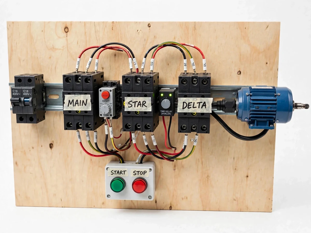
A star-delta starter is a reduced-voltage starter that limits the heavy inrush current of a 3-phase induction motor at start-up. Across the supply directly (direct-on-line starting), it can draw five to seven times its rated current, dipping the supply voltage and stressing windings and switchgear; the star-delta method first connects the windings in star, so each sees only 1/√3 of the line voltage (about 58%), and starting line current and torque fall to roughly one-third of their direct-on-line values. Once the motor accelerates, a timer relay automatically reconnects the windings in delta for full-voltage running. This project builds the complete starter as a single demonstrator panel: three contactors (main, star and delta), a dial-adjustable timer relay, a thermal overload relay, an MCB, and a green-start/red-stop push-button station. Star and delta contactors are electrically and mechanically interlocked so both can never close together, and the changeover delay is about 8 seconds for the demo motor.
How it works
From supply to running motor, the full sequence takes under ten seconds. With the MCB on, supply reaches the main contactor and the control circuit is live, but nothing moves until the green start button is pressed. Start energizes the main and star contactors — the windings are now in star across the supply, each seeing 1/√3 of the line voltage, so the motor accelerates gently at about one-third of direct-on-line current — a seal-in contact holding both contactors after the button is released. The same start signal triggers the on-delay timer relay, which counts its set delay (about 8 s in this build), its LED indicating timing. When the delay elapses, the timer drops the star contactor and the interlock chain pulls in the delta contactor: the windings reconnect in delta at full line voltage and the motor runs at rated speed. Stop, or an overload trip, drops the main contactor and everything de-energizes.
- Switch on the 3-pole MCB — the 3-phase supply reaches the main contactor terminals and the control circuit is energized, with all contactors open.
- Press the green start push button — the main and star contactors energize together, and a seal-in auxiliary contact keeps them energized after the button is released.
- The motor windings are now connected in star across the supply; each winding sees 1/√3 of the line voltage (about 58%), so starting line current and torque are roughly one-third of direct-on-line values (design target).
- The timer relay starts counting its set delay from the same start signal — about 8 s in this build, adjustable on the relay dial from 0.1 s to 60 s (datasheet value).
- When the delay elapses, the timer relay de-energizes the star contactor; the interlock chain then permits the delta contactor to pull in, reconnecting the windings in delta for full-voltage running.
- The motor runs in delta at rated speed; the timer relay's LEDs and the contactor states on the panel show the running condition.
- If the motor draws sustained overcurrent, the thermal overload relay trips and drops the main contactor; the red reset button must be pressed before restarting.
- Pressing the red stop button (or switching off the MCB) de-energizes all contactors and the motor coasts to a stop.
Tech stack:
- 3-pole AC contactors × 3 (main · star · delta)
- Electronic on-delay timer relay (0.1–60 s dial)
- Thermal overload relay with manual reset
- 3-pole MCB incomer
- Green start · red stop push-button station
- 3-phase induction motor (demo load)
- DIN rail · ferruled control and power wiring
- Power + control wiring diagrams
| Parameter | Value |
|---|---|
| Supply | 415 V AC, 3-phase, 50 Hz (typical) |
| Demo motor | 0.37 kW (0.5 HP), 3-phase induction (demo unit; sized to order) |
| Phase voltage in star | 1/√3 of line voltage, ≈ 58% (design target) |
| Starting line current (star) | ≈ 1/3 of direct-on-line value (design target) |
| Starting torque (star) | ≈ 1/3 of direct-on-line value (design target) |
| Changeover delay | 0.1–60 s dial range (datasheet value); ≈ 8 s in this build |
| Timer relay supply | 24 V AC/DC (datasheet value) |
| Control circuit | 230 V AC, 50 Hz (typical) |
| Overload relay range | Selected to suit the motor; 4–6 A in this build (typical) |
| Panel construction | Plywood backplate, DIN-rail mounted components (prototype build) |
Project features
The three capabilities that make this build worth demonstrating are automatic timer changeover, fail-safe interlocking, and genuine overload protection. The electronic timer relay takes the changeover decision out of the operator's hands: the delay is set on a dial (0.1–60 s on the fitted relay, about 8 s in this build), the relay's LEDs show the timing state, and the star-to-delta transition happens the same way every start. Safety comes from two independent interlocks — auxiliary-contact electrical interlocking plus a mechanical interlock between the star and delta contactors — so the one wiring fault that would dead-short the supply is structurally impossible. Protection is completed by a thermal overload relay matched to the motor current, with manual reset after a trip, and an MCB incomer for short-circuit faults. Together with the labelled DIN-rail layout and ferruled wiring, the panel reads as a real industrial starter shrunk to lab scale, which is exactly what examiners want to probe.
- [Automatic timer changeover] The on-delay timer relay counts the set delay from the moment the motor starts in star, then drops the star contactor and pulls in the delta contactor without any manual switching — the dial setting used in this build is about 8 s.
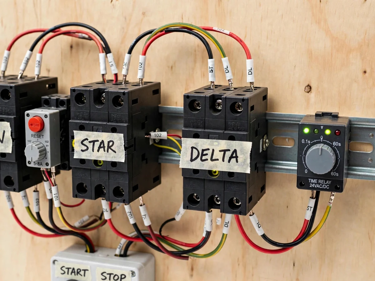
- [Three-contactor power circuit] Main, star and delta contactors form the classic power circuit; each carries a handwritten masking-tape label and the power wiring uses ferruled red, black and yellow-green conductors in standard phase and earth colours.
- [Dual interlocking] The star and delta contactors are interlocked both electrically (through each other's auxiliary contacts) and mechanically, so both can never close together — the single most dangerous fault in this circuit is prevented by construction, not just by wiring care.
- [Thermal overload protection] A thermal overload relay in the main circuit trips on sustained overcurrent from mechanical overload or single-phasing, with a red reset button that must be pressed manually before the motor can be restarted.
- [MCB incomer and push-button station] A 3-pole MCB provides short-circuit protection at the panel incomer, and the green start / red stop station uses a seal-in contact so the motor keeps running after the start button is released until stop is pressed.
- [Live status indication] The timer relay's LEDs show timing and changeover state, and the contactors' mechanical state is visible on the panel, so the start → star → changeover → delta sequence can be watched and explained during the demonstration.
- [Wired demo motor] A small 3-phase induction motor is wired to the panel as the demonstration load, so the reduced-voltage start and the changeover moment are visible and audible rather than theoretical.
What is included
- Fully wired star-delta starter panel (3 contactors, timer relay, overload relay, MCB, push-button station)
- Small 3-phase induction motor wired as the demonstration load
- Power and control wiring diagrams
- Project report PDF (theory, working principle, calculations, test procedure)
- PPT presentation for the final review
- Viva Q&A preparation document
- Component list with datasheet references
Limitations & prerequisites
- Star starting reduces starting torque to about one-third of direct-on-line, so it is unsuitable for loads needing high breakaway torque unless the motor is oversized for the job.
- This is an open-transition starter: there is a brief current transient at the star-to-delta instant, unlike a closed-transition or soft starter.
- The demonstration uses a small fractional-kW motor and needs a 3-phase supply; a single-phase-only lab cannot run it without a phase converter.
- The changeover delay is a fixed dial setting chosen at commissioning — it does not adapt to load or inertia.
- The panel is a plywood-mounted lab prototype, not a certified industrial control panel, and 3-phase work involves lethal voltages — demonstration needs supervision and standard lab safety practice.
- Contactor and relay brands/models vary with availability; the circuit topology and documented ratings stay as specified.
Frequently Asked Questions
How does the star connection actually cut the starting current?
In star, each motor winding is connected between one supply phase and the star point, so it sees the phase voltage — the line voltage divided by √3, about 58%. Since current is proportional to voltage, the line current falls to about one-third of the direct-on-line value. After the motor accelerates, the windings are reconnected in delta across the full line voltage for normal running.
That one-third figure is the textbook design target for the ideal case; the built panel demonstrates the reduced-voltage start on a live motor, so the gentler acceleration is visible instead of theoretical.
What does the timer relay do, and can the delay be changed?
The timer relay automates the star-to-delta changeover. When the motor starts in star, the on-delay timer begins counting; when the delay elapses it drops the star contactor and pulls in the delta contactor, so the motor moves to full-voltage running without any manual switching. The delay is set on the relay's dial — the fitted relay covers 0.1 s to 60 s, and this build uses about 8 s.
Choose a delay long enough for the motor to reach near-rated speed in star, but not so long that it lingers at reduced torque — the report documents how to select it for a different motor rating.
Why does the starter need three contactors?
Each contactor has one job the others cannot do. The main contactor connects and disconnects the supply; the star contactor joins the winding ends to form the star point during starting; the delta contactor cross-connects the winding ends to form delta for running. Star and delta must never be closed together — that would short the supply — so they are electrically and mechanically interlocked, hence three contactors, not one.
Using separate contactors is also what lets the timer relay switch the winding configuration automatically while the main contactor stays closed throughout.
What happens if the star and delta contactors close together?
Closing both would connect the supply phases directly across each other through the contactor poles — a dead short circuit that would trip the MCB and could weld or destroy the contactors. That is exactly why this build interlocks them twice: auxiliary contacts in the control circuit prevent one coil from energizing while the other is closed, and a mechanical interlock physically blocks simultaneous closure.
The fault is prevented by construction, not by careful operation — which is the point examiners usually probe.
Is this project suitable for a final-year project?
Yes — for Electrical and Electronics programs. It covers electrical machines (the 3-phase induction motor), power circuits (contactor logic, interlocking), protection (overload relay, MCB) and control wiring, all demonstrated on a live panel that examiners can probe during the viva. The report documents the star-delta theory with the 1/√3 derivation, the wiring diagrams, and a test procedure, so the viva has real material to work with.
The build also demonstrates practical skills — ferruled wiring, DIN-rail layout, component selection from datasheets — that map directly to industrial panel work.
Components & software requirements
- 3-pole AC contactors × 3 (main · star · delta)
- Electronic on-delay timer relay (0.1–60 s dial)
- Thermal overload relay with manual reset
- 3-pole MCB incomer
- Green start · red stop push-button station
- 3-phase induction motor (demo load)
- DIN rail · ferruled control and power wiring
- Power + control wiring diagrams
Delivery information
Built-to-order project. Delivery timeline is shared after order confirmation based on current queue.
Support terms
Complete documentation, setup guide, and viva preparation included. Support for setup and explanation provided.
Download free synopsis (PDF)
Enter your name and WhatsApp number — the synopsis PDF downloads immediately. We may send occasional project updates on WhatsApp; no spam.