
More project photos (3)
The problem
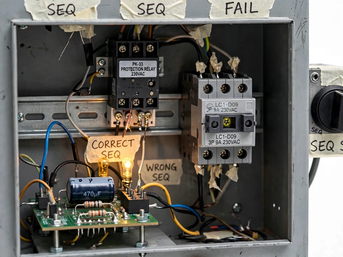
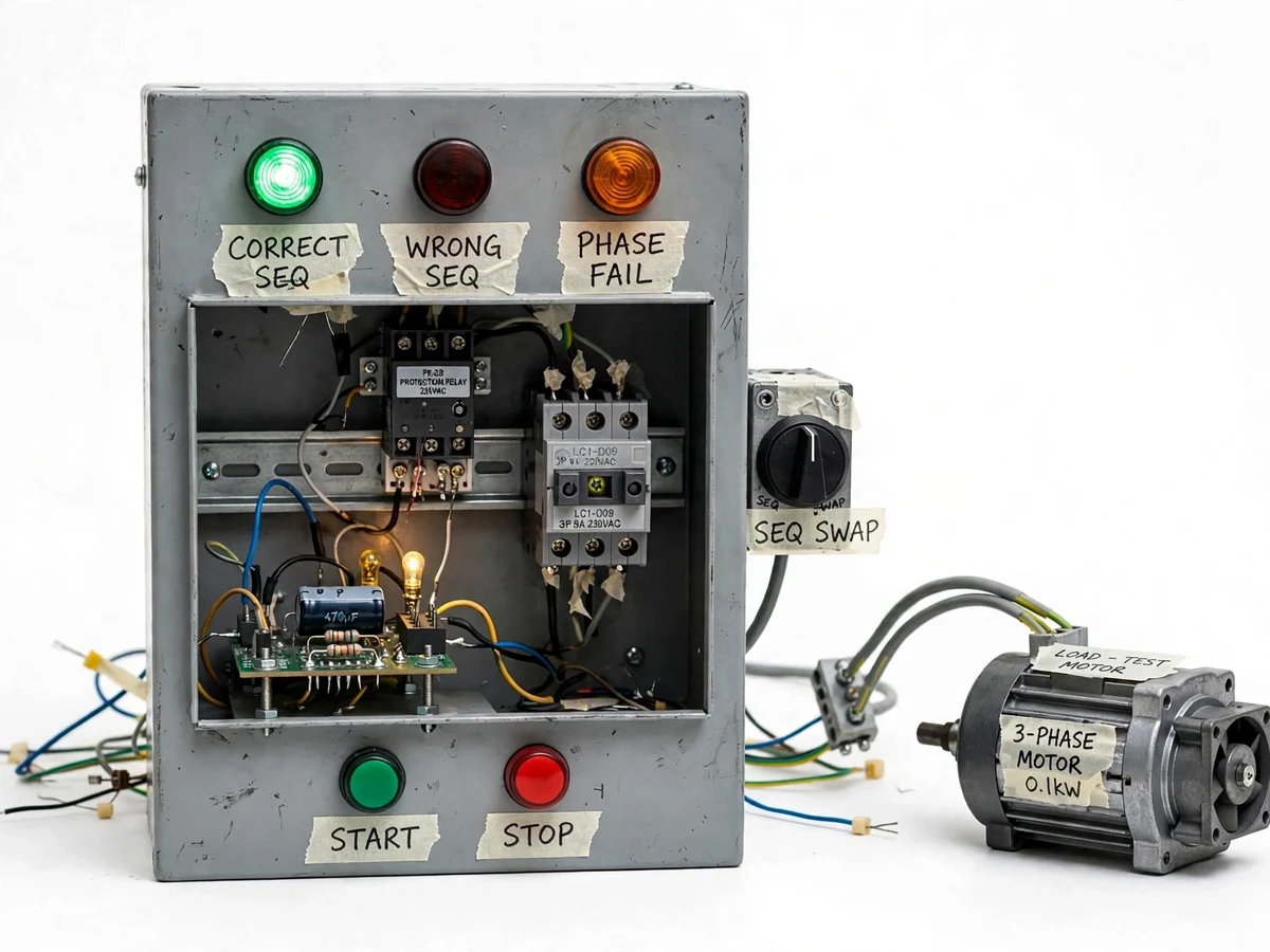
Three-phase motors do not care which wire is "first" — but they absolutely care about the order. Swap any two phases and the rotating field reverses: a pump runs backwards and delivers nothing, a compressor can be damaged, a conveyor runs the wrong way into its stops. Phase-sequence relays exist precisely for this, yet students usually meet them only as a symbol on a single-line diagram. This project builds the function from first principles: a classic RC phase-shift network (two lamps/resistors and a capacitor across the three phases) whose lamp brightness directly reveals the sequence, feeding a detector that drives CORRECT/WRONG SEQUENCE lamps and a protection relay wired into the motor contactor's coil circuit. A panel-mounted sequence-swap switch lets the examiner flip RYB to RBY live and watch the panel block the start. The student builds real protection logic — detection, indication, blocking — around one of the subtlest three-phase concepts in the syllabus.
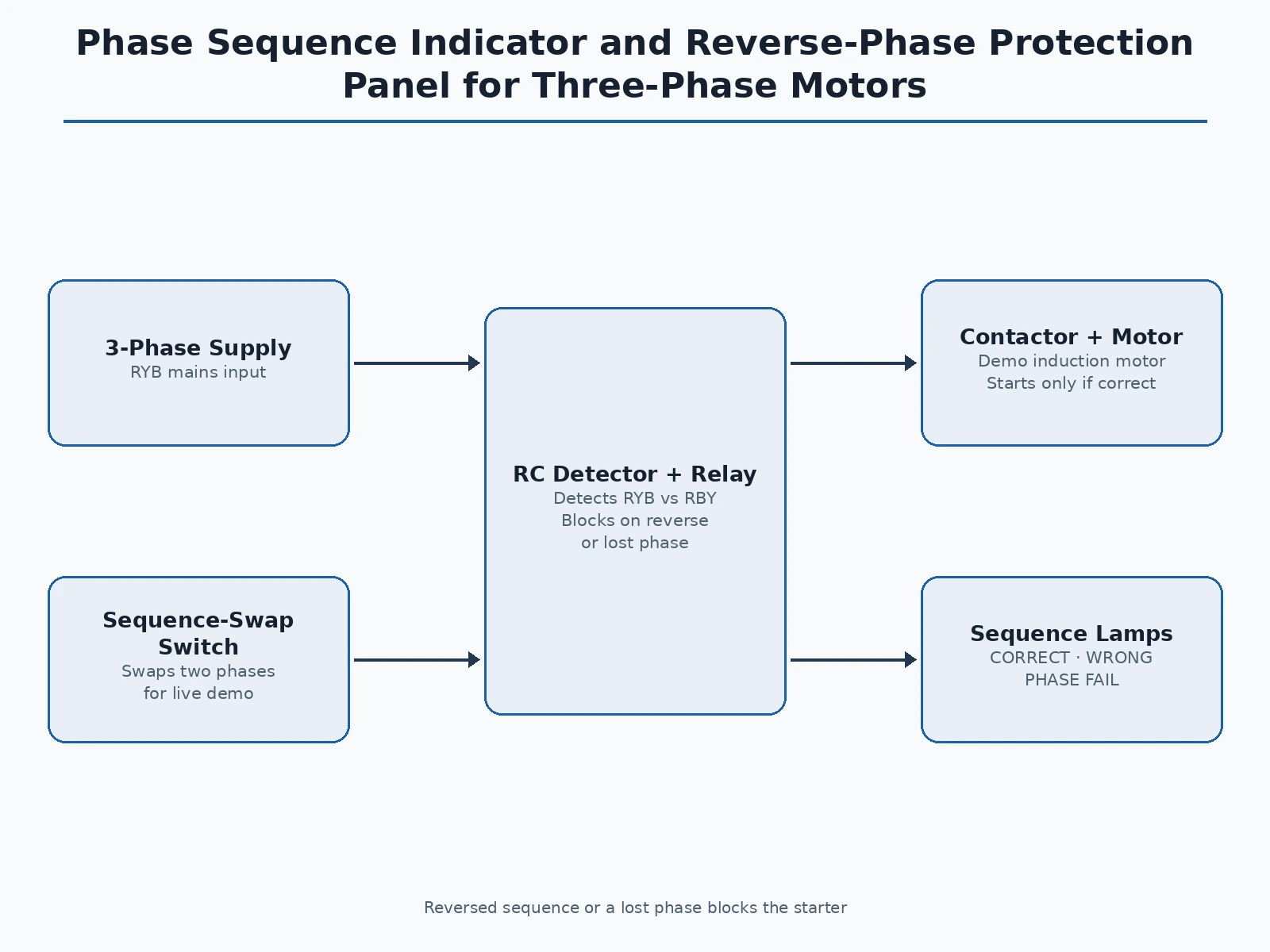
Feeds the RC detector network.
Follow the working sequence
How it works
- The three supply phases feed the RC detector network: two equal resistors (with indicator lamps) and a capacitor connected phase-to-phase in the classic sequence-indicator arrangement.
- With correct RYB sequence, the capacitor's phase shift makes one lamp bright and the other dim in a known pattern; with RBY sequence the pattern inverts — the detector reads this unbalance.
- A comparator/relay stage converts the unbalance into a clean CORRECT or WRONG SEQUENCE lamp output on the panel.
- The WRONG SEQUENCE state energizes the protection relay, whose NC contact sits in the motor contactor's coil circuit — the motor cannot start, or trips if running.
- Loss of any phase collapses the network voltages, which the detector reads as a fault: the PHASE FAIL lamp lights and the contactor is blocked the same way.
- Flipping the panel's sequence-swap switch exchanges two phases upstream of the detector, letting the examiner demonstrate the full detect–indicate–block chain live.
- On restoring correct sequence, the panel re-arms automatically and the motor can be started normally from the push-button station.
Tech stack:
- RC phase-shift detector network (resistors, capacitor, indicator lamps)
- Comparator / relay detector stage
- Protection relay with contacts in the contactor coil circuit
- 3-pole motor contactor + start/stop push-buttons
- Sequence-swap demonstration switch
- CORRECT / WRONG SEQUENCE / PHASE FAIL lamp set
- Small three-phase demonstration motor
- Steel panel, 415 V three-phase input (demo scale), control wiring
| Parameter | Value |
|---|---|
| Detection method | RC phase-shift network, lamp-unbalance principle |
| Sequences detected | RYB (correct) vs RBY (reversed) |
| Additional protection | Phase-loss (single-phasing) blocking |
| Output | Protection relay → motor contactor coil circuit |
| Demo motor | Small 3-phase induction motor, approximately 0.25 HP (design) |
| Indication | 3 lamps: correct / wrong sequence / phase fail |
| Demo control | Panel sequence-swap switch for live reversal |
| Response | Blocking is effectively instantaneous on sequence change (design) |
Project features
- [RC phase-sequence detector] The classic two-lamp/capacitor network across the three phases — lamp brightness unbalance directly indicates RYB vs RBY sequence, built exactly as in textbooks.
- [Correct/wrong sequence lamps] Green CORRECT SEQUENCE and red WRONG SEQUENCE lamps give an instant, examiner-visible indication of the supply order.
- [Reverse-phase blocking] A protection relay in series with the motor contactor coil blocks starting (and trips a running motor) on reversed sequence — the core protective function.
- [Phase-loss detection] The same detector network unbalances on a lost phase, so single-phasing also blocks the starter, with a PHASE FAIL lamp.
- [Sequence-swap demo switch] A panel switch swaps two phases on demand, so the examiner can flip the sequence live and watch the protection operate.
- [Motor contactor output] The protection relay drives a real contactor feeding a small three-phase demonstration motor, so blocked vs allowed starts are visible.
- [Tested indication logic] A step-by-step commissioning procedure verifies each lamp and the blocking action against known sequence states.
What is included
- Complete phase-sequence protection panel with detector network and contactor
- Demonstration motor with push-button start/stop station
- Detector theory note (why the RC network unbalances with sequence)
- Wiring diagram and panel layout drawing
- Commissioning and demonstration procedure (known-sequence verification steps)
- Project report PDF (background, sequence theory, detector design, protection wiring, tests)
- PPT presentation for final review
- Viva Q&A preparation document (rotating field, sequence vs phase loss, detector math, relay wiring)
Limitations & prerequisites
- Demonstrates the protection principle at bench scale on a small motor; industrial sequence relays add features (adjustable delays, regeneration blocking) covered in the theory note.
- The RC detector needs a reasonably balanced three-phase supply to indicate cleanly; heavily unbalanced supplies blur the lamp pattern, and the report explains why.
- Designed for demonstration voltages and a small motor — not a certified protection relay for plant motors.
- The detector indicates sequence at the panel terminals; a phase swap downstream of the panel is outside its sensing point, noted in the manual.
- Component values in the RC network are design targets tuned on the bench build; the commissioning procedure verifies indication against known sequences.
Frequently Asked Questions
Why does phase sequence matter if the motor runs on any three phases?
Because the order of the phases sets the direction of the rotating magnetic field. RYB spins the motor one way; RBY spins it the opposite way — so a phase swap after maintenance can run a pump backwards or drive a conveyor into its stops.
How does the lamp-capacitor network detect sequence?
The capacitor shifts its branch current by 90°, so the voltage divides unequally across the two lamp branches — and which lamp gets the higher voltage flips when the phase order reverses. It is the textbook sequence indicator, built for real.
What does the panel do on wrong sequence — just warn?
It blocks. The protection relay opens the motor contactor's coil circuit, so the motor cannot be started (or is tripped if running). Indication alone would rely on the operator noticing; blocking is the protection function.
Does it also catch a lost phase?
Yes — losing a phase collapses the detector network voltages, which reads as a fault state: the PHASE FAIL lamp lights and the starter is blocked, giving single-phasing protection as a bonus.
How is it demonstrated in the viva?
The panel's sequence-swap switch exchanges two phases live: the examiner watches the lamps flip from CORRECT to WRONG SEQUENCE and the motor start get blocked, then restores the sequence and starts the motor normally.
Is this project suitable for a final-year project?
Yes — for Electrical Engineering programs. It converts a subtle three-phase concept into a working protection panel with detection, indication and blocking the student can trigger and explain. Suitable for B.E./B.Tech final-year projects in Electrical Engineering.
Components & software requirements
- RC phase-shift detector network (resistors, capacitor, indicator lamps)
- Comparator / relay detector stage
- Protection relay with contacts in the contactor coil circuit
- 3-pole motor contactor + start/stop push-buttons
- Sequence-swap demonstration switch
- CORRECT / WRONG SEQUENCE / PHASE FAIL lamp set
- Small three-phase demonstration motor
- Steel panel, 415 V three-phase input (demo scale), control wiring
Delivery information
Built-to-order project. Delivery timeline is shared after order confirmation based on current queue.
Support terms
Complete documentation, setup guide, and viva preparation included. Support for setup and explanation provided.
Download free synopsis (PDF)
Enter your name and WhatsApp number — the synopsis PDF downloads immediately. We may send occasional project updates on WhatsApp; no spam.