
More project photos (2)
The problem
A three-phase induction motor rotates forward only when its supply arrives in the correct RYB sequence. Whenever phases are interchanged — after maintenance, a generator changeover, or a loose reconnection — the motor runs in reverse, which can damage pumps, fans, conveyors and lifts, or stop sequence-protected equipment entirely. Worse, if one phase is lost while running, the motor single-phases: the remaining windings carry excess current and the motor overheats and burns out. Manual correction needs an electrician on site and costs downtime. This project builds a control panel that automates the fix: a phase-sequence-and-failure relay continuously watches the incoming supply, and through two interlocked contactors it guarantees the motor terminals always see the correct sequence — disconnecting the motor if a phase is lost. For a student, it is a complete, hands-on build of sensing, relay logic, contactor control circuits and safe panel wiring in one project.
Incoming R/Y/B supply entering the panel through the main MCB.
Follow the working sequence
How it works
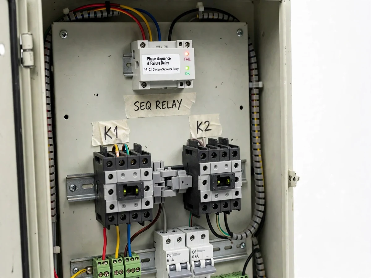
- The incoming R/Y/B supply enters the panel through the main MCB and feeds the sequence relay's sensing terminals and the line terminals of both contactors.
- When all three phases are present in the correct order, the relay's healthy output energizes contactor K1, which passes R-Y-B straight through to the motor terminals.
- If the input sequence is reversed, the relay drops K1 and energizes K2 instead; K2's power wiring crosses two phases, so its output is R-Y-B again.
- If any phase is lost, the relay's fault output de-energizes both K1 and K2 — the motor is disconnected, the red fault lamp lights, and the alarm contact closes.
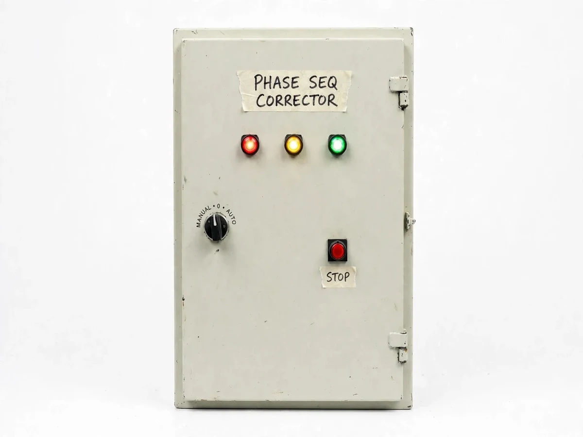
- The selector switch on the door chooses AUTO (the relay decides), MANUAL (K1 forced on), or 0/OFF (both contactors locked out).
- Pilot lamps show phase presence and healthy/fault status; the MCBs guard the control and motor branches against short circuits.
Tech stack:
- Phase sequence & failure relay module
- 2 × AC-3 contactors, 415 V coil
- Mechanical interlock block
- C-curve MCBs
- 22 mm LED pilot lamps · selector switch · push buttons
- DIN rail · terminal blocks · cable ducts
- Mild-steel control panel enclosure
- R/Y/B copper panel wiring with ferrules
| Parameter | Value |
|---|---|
| Rated input voltage | 415 V AC, 3-phase (design target) |
| Supply frequency | 50 Hz (design target) |
| Motor rating | Up to 5 HP three-phase induction motor (design target) |
| Main contactors | Two, AC-3 duty, 415 V coil (datasheet values of fitted contactors) |
| Sequence sensing | Phase order + phase loss via relay module; correction in under 1 s (design target) |
| Correction method | K1 direct / K2 phase-swapped changeover |
| Interlocking | Mechanical + electrical — simultaneous closure prevented by construction |
| Branch protection | C-curve MCBs on control and motor branches (ratings component-dependent) |
| Indication | R/Y/B supply, healthy and fault pilot lamps, 22 mm LED (datasheet) |
| Enclosure | Mild-steel panel, approximately 400 × 300 × 150 mm (approximate) |
Project features
- [Automatic sequence correction] When the relay senses a reversed input sequence, it drops K1 and closes K2; K2's power wiring crosses two phases, so the motor terminals still receive R,Y,B without anyone touching the panel.
- [Single-phase prevention] On loss of any phase, the relay de-energizes both contactors to disconnect the motor instead of letting it single-phase; a red fault lamp lights and the alarm contact closes.
- [Interlocked reversing contactors] K1 and K2 are fitted with a mechanical interlock and wired with electrical interlocking in the control circuit, so both contactors can never close at the same time — a phase-to-phase short is prevented by construction.
- [MCB protection] Dedicated MCBs protect the control circuit and the motor branch against short circuits and sustained overcurrent, with ratings matched to the contactors fitted.
- [Panel indication] R/Y/B supply lamps plus green healthy and red fault pilot lamps on the door show the panel state at a glance.
- [Manual / auto / off selector] The door-mounted selector switch gives relay-controlled automatic correction, forced manual running on K1, or a locked-off position for safe maintenance.
- [Trip and alarm output] A potential-free relay contact is brought to terminals for an external hooter or PLC alarm input.
What is included
- Working automatic phase sequence corrector panel prototype (enclosure, relay, contactors, MCBs, lamps, selector switch, wired and tested)
- Power and control wiring diagrams with terminal numbering
- Component list with ratings and datasheets
- Commissioning and testing procedure, including verification against a known-correct supply
- Project report PDF (background, relay theory, contactor interlocking, methodology, tests)
- PPT presentation for final review
- Viva Q&A preparation document (sequence, single-phasing, interlocking, protection coordination)
Limitations & prerequisites
- The panel corrects sequence; it does not regulate voltage — low, high or imbalanced supply voltages are passed through to the motor.
- Single-phase prevention is not overload protection; sustained overload still needs a thermal overload relay (offered as a customization).
- The prototype is a design target for motors up to about 5 HP at 415 V; larger ratings need bigger contactors and a larger enclosure.
- Correction depends on the relay module's sensing, so the commissioning procedure must be run against a verified correct supply before first use.
- This is an academic prototype, not a certified industrial panel; connection to live plant wiring must be done by a qualified electrician.
- Relay modules switch within their datasheet delay, not instantly; supply dips shorter than that delay pass through unchanged.
Frequently Asked Questions
How does the panel correct a reversed phase sequence?
The sequence relay watches the order of the three incoming phases. On a correct R,Y,B input it closes contactor K1, which passes the supply straight through. On a reversed input it drops K1 and closes K2 instead — K2's power wiring crosses two phases, so the motor terminals still receive R,Y,B. The changeover is fully automatic.
What happens if one phase is lost?
The panel does not attempt correction — single-phasing would overheat the motor. The sequence relay detects the missing phase, drops both K1 and K2 to disconnect the motor, lights the red fault lamp and closes the alarm contact. The motor is re-energized only after all three phases return.
How is this different from a phase sequence indicator?
An indicator only detects and displays the sequence and leaves correction to a person. This panel is indication-plus-action: the same sensing signal drives two interlocked contactors that physically swap two phases, so the corrected sequence reaches the motor by itself. It also disconnects the load on phase loss.
What supply and motor size does the prototype support?
The design target is 415 V, 50 Hz, 3-phase supplies driving induction motors up to about 5 HP, using AC-3 duty contactors. Final ratings are component-dependent — the MCBs and contactors fitted at build time set the limits, and larger contactors and enclosure can be specified as a customization.
How is the panel commissioned and tested safely?
First the wiring is checked against a known-correct 3-phase supply: in manual mode the healthy lamp must glow and K1 must close. Then the input leads are deliberately interchanged to confirm K2 takes over, and one phase is removed to confirm the trip. All live testing requires qualified supervision at 415 V.
Is this project suitable for a final-year project?
Yes, for Electrical Engineering and E&TC students. It demonstrates three-phase power fundamentals, protection relaying, contactor control circuits, electrical interlocking practice and safe panel wiring — a complete build, not a simulation. The report documents the wiring diagram, tests and limitations for the viva.
Components & software requirements
- Phase sequence & failure relay module
- 2 × AC-3 contactors, 415 V coil
- Mechanical interlock block
- C-curve MCBs
- 22 mm LED pilot lamps · selector switch · push buttons
- DIN rail · terminal blocks · cable ducts
- Mild-steel control panel enclosure
- R/Y/B copper panel wiring with ferrules
Delivery information
Built-to-order project. Delivery timeline is shared after order confirmation based on current queue.
Support terms
Complete documentation, setup guide, and viva preparation included. Support for setup and explanation provided.
Download free synopsis (PDF)
Enter your name and email — the synopsis PDF downloads immediately. We may send occasional project updates; no spam, unsubscribe anytime.