
More project photos (2)
The problem
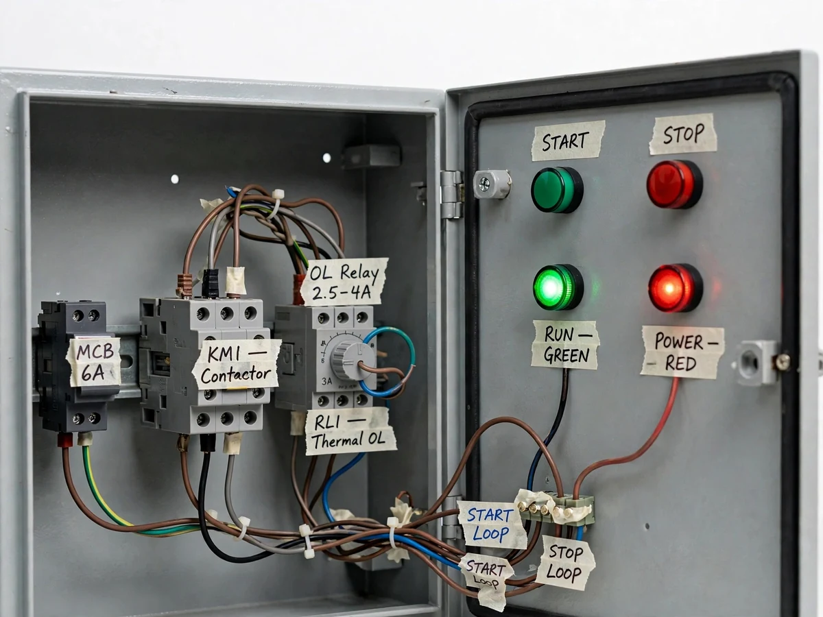
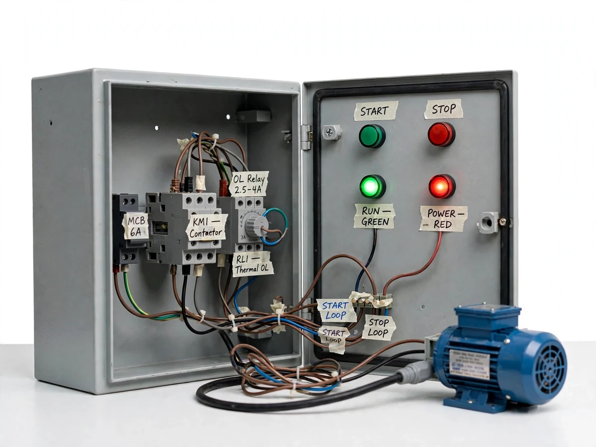
The direct-on-line starter is the first motor-control circuit every electrical student must master: it connects a three-phase induction motor straight across the supply through a contactor, holds the contactor closed with its own auxiliary contact, and protects the motor with a thermal overload relay. It is also the circuit most often taught only as a ladder diagram on a whiteboard. This project turns that diagram into a wired, working panel — a steel enclosure containing a three-phase contactor, a thermal overload relay, an MCB for short-circuit protection, a green start and red stop pushbutton, and indicator lamps, all wired to a small induction motor. By pressing start, watching the contactor seal in, and tripping the overload relay on purpose, students see the control logic they drew in class operating in hardware, including the fault states that the diagram never shows.
How it works
- Three-phase 415 V supply enters the panel through the MCB and isolator to the contactor's main contacts and the control circuit.
- Pressing the green start button energizes the contactor coil; its auxiliary contact seals the circuit so the button can be released and the motor keeps running.
- The run lamp lights and the motor accelerates direct-on-line, drawing its normal starting current through the contactor.
- The thermal overload relay continuously senses motor current; if it exceeds the set value for the trip time, the relay opens its NC contact in the control circuit.
- The contactor drops out, the motor stops, and the fault lamp shows the overload-tripped state — pressing start again does nothing until the relay is reset.
- After the overload relay cools, pressing its manual reset restores the control circuit, and a normal start sequence can run again.
Tech stack:
- 3-pole contactor with auxiliary contacts
- Thermal overload relay (adjustable range)
- 3-phase MCB and isolator
- Green start · red stop pushbuttons
- Run/fault indicator lamps
- Sheet-steel panel enclosure
- Three-phase induction motor (demo rating)
| Parameter | Value |
|---|---|
| Supply | 415 V AC, 3-phase, 50 Hz (design) |
| Contactor | 3-pole, AC-3 duty, datasheet-rated |
| Overload relay | Adjustable range, manual reset (datasheet) |
| Protection | MCB for short-circuit, OLR for overload |
| Control | 230 V AC coil circuit via pushbuttons |
| Indication | Supply, run and overload-trip lamps |
| Motor | Three-phase induction, demo rating (design) |
| Enclosure | Indoor sheet-steel panel (design) |
Project features
- [Real contactor starter circuit] A three-phase contactor switches the motor supply, wired exactly per the standard DOL starter ladder diagram used in industry.
- [Seal-in (hold-on) logic] The contactor's auxiliary contact holds the coil energized after the start button is released, demonstrating the latching behaviour examiners always ask about.
- [Thermal overload relay] An overload relay in the motor circuit trips on sustained overcurrent, with a manual reset that teaches the difference between fault trip and normal stop.
- [Start/stop pushbutton station] Green start and red stop buttons on the panel door give the operator interface every motor starter has.
- [Run and fault indication] Indicator lamps show supply-healthy, motor-running and overload-tripped states at a glance.
- [MCB short-circuit protection] An MCB upstream of the contactor protects the panel wiring, showing how control and protection devices are coordinated.
- [Safe demo motor] A small three-phase induction motor is supplied wired to the panel, so the full start-run-trip sequence runs on the bench.
What is included
- Fully wired DOL starter control panel in a steel enclosure
- Three-phase induction motor wired to the panel for bench demonstrations
- Complete wiring diagram and ladder diagram of the starter circuit
- Operating procedure (start, normal stop, overload trip and reset)
- Overload relay setting guide for the supplied motor
- Project report PDF (starter theory, control logic, methodology, observations)
- PPT presentation for final review
- Viva Q&A preparation document (seal-in logic, contactor vs relay, overload vs short-circuit protection)
Limitations & prerequisites
- DOL starting is suitable only for the small demo motor supplied; larger motors need reduced-voltage starters, which the report explains.
- The demonstration motor runs unloaded on the bench; loaded-motor behaviour is described from theory, not measured.
- Overload trip times follow the relay's thermal characteristic — the demo uses deliberate overload settings, not a real motor fault.
- The panel is for indoor lab demonstration; it is not a certified industrial starter installation.
Frequently Asked Questions
What is a DOL starter, and when is it used?
Direct-on-line starting connects the motor straight across the full supply voltage. It is the simplest starter, used for small motors where the high starting current does not disturb the supply — typically up to a few kW on industrial supplies.
How does the seal-in contact work?
The contactor's own auxiliary contact is wired in parallel with the start button. Once the coil energizes, this contact closes and keeps the coil energized after the button is released — so the motor keeps running without anyone holding the button.
What is the difference between the MCB and the overload relay?
The MCB trips almost instantly on short-circuit current to protect the wiring; the thermal overload relay trips after a time delay on moderate sustained overcurrent to protect the motor windings from overheating. They do different jobs and the panel shows both.
Why does the panel refuse to start after an overload trip?
The overload relay's NC contact stays open in the control circuit until the relay is manually reset after cooling. This lockout behaviour prevents repeated hot restarts that would damage a real motor.
Can this start a bigger motor?
Not as built — the contactor, overload range and wiring are sized for the supplied demo motor. The documentation includes the sizing procedure so students learn how a starter is selected for any motor rating.
Is this project suitable for a final-year project?
Yes — for Electrical and Electronics engineering programs. It is the foundational motor-control circuit built as real hardware, with control logic, protection coordination and wiring practice in one panel. Suitable for B.E./B.Tech final-year projects in Electrical and Electronics engineering.
Components & software requirements
- 3-pole contactor with auxiliary contacts
- Thermal overload relay (adjustable range)
- 3-phase MCB and isolator
- Green start · red stop pushbuttons
- Run/fault indicator lamps
- Sheet-steel panel enclosure
- Three-phase induction motor (demo rating)
Delivery information
Built-to-order project. Delivery timeline is shared after order confirmation based on current queue.
Support terms
Complete documentation, setup guide, and viva preparation included. Support for setup and explanation provided.