
More project photos (2)
The problem
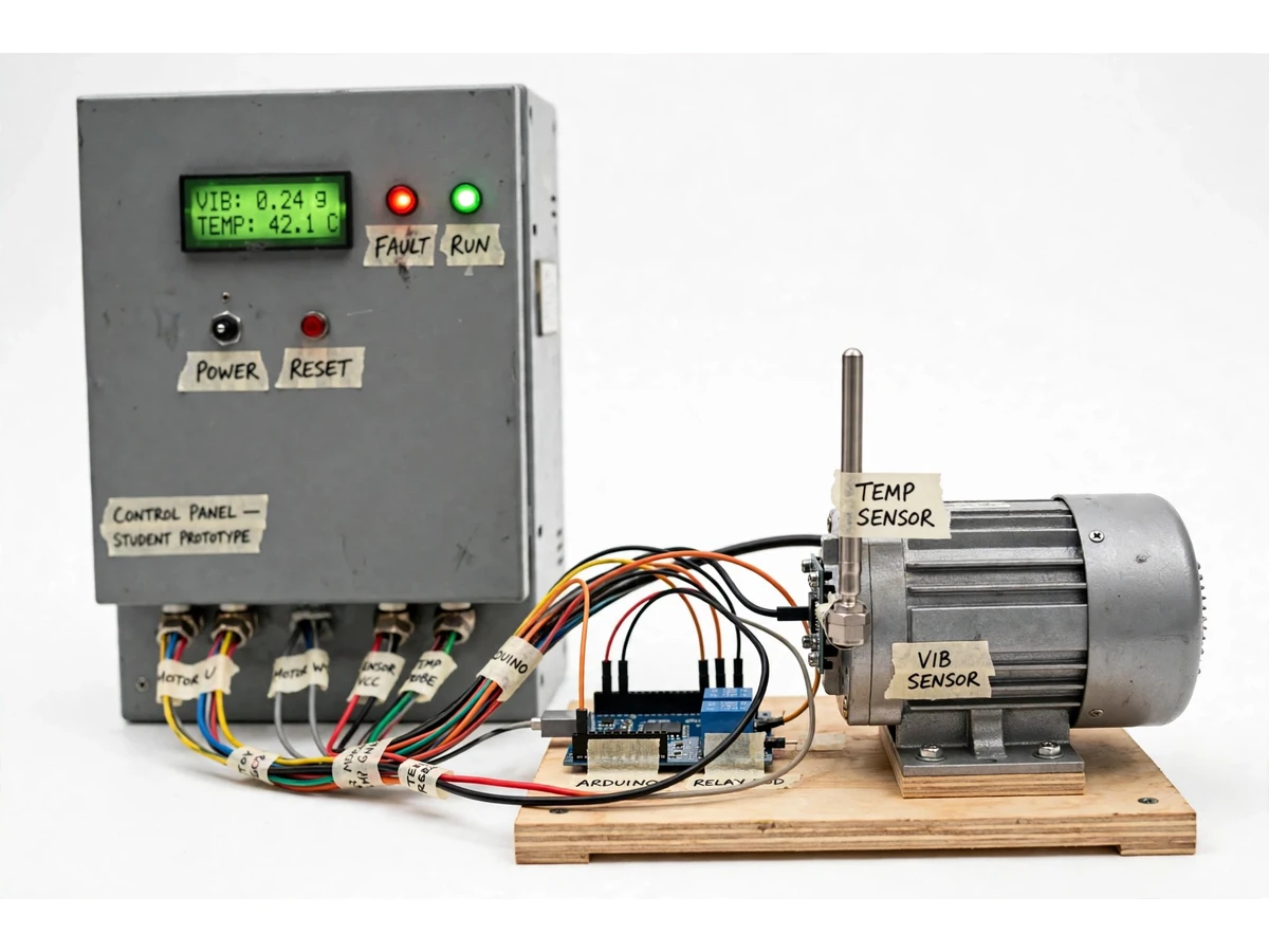
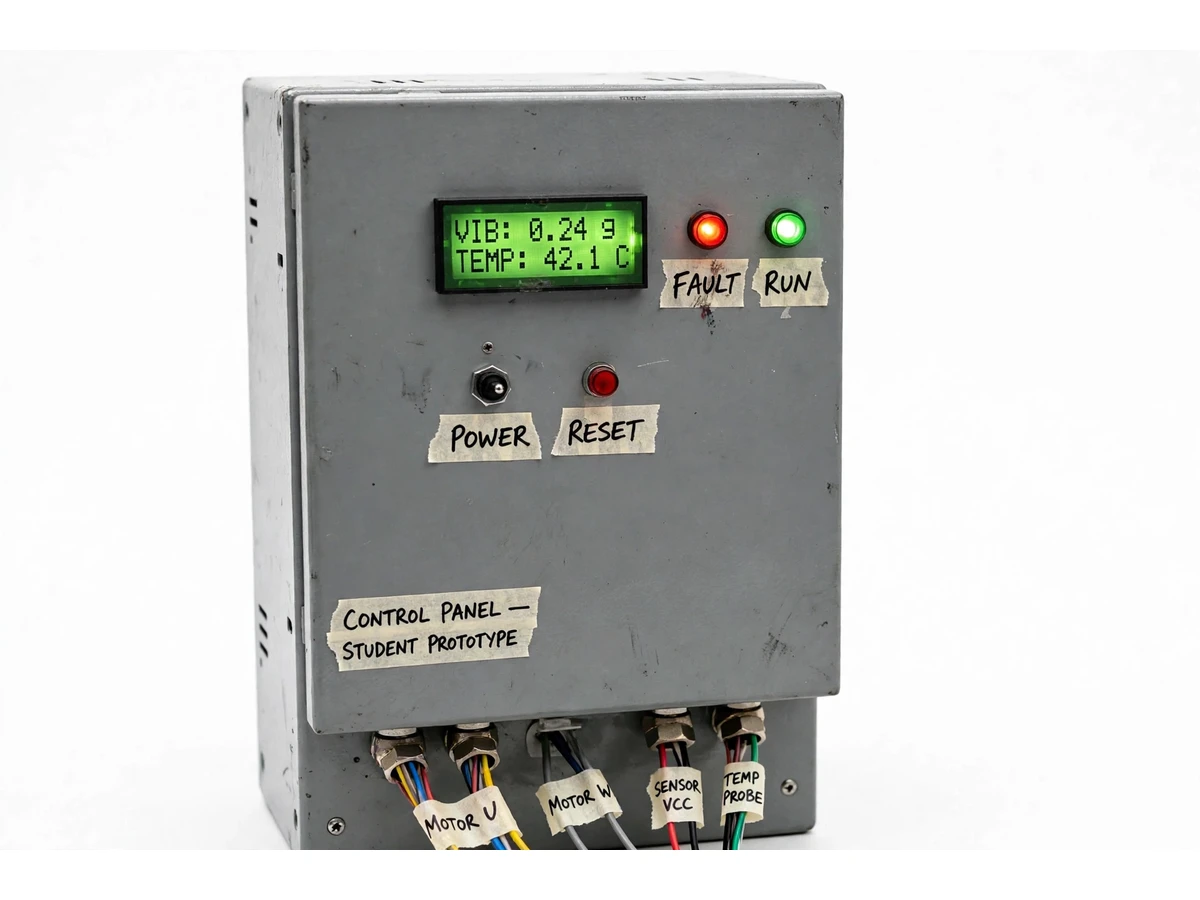
The Three-Phase Induction Motor Fault Diagnosis Panel with Vibration and Temperature Sensing is a bench panel that watches a small three-phase induction motor and names the fault when something goes wrong, instead of only switching the motor off. A vibration sensor bolted to the motor frame and a temperature probe on the motor body feed an Arduino controller, which compares both readings against set thresholds and classifies the condition as healthy, vibration fault, overheating fault, or combined fault. The result appears on a 16x2 LCD with green RUN and red FAULT lamps, a buzzer sounds on a fault, and a relay trips the motor contactor while the fault stays latched until manual reset. The mechanism is first-principles: a damaged bearing produces repeated impacts once per revolution, so its vibration rises in sharp, repeating bursts rather than smoothly, while overheating shows as a slow, steady climb in frame temperature that vibration alone would miss.
Three-phase induction motors drive pumps, fans, conveyors and machine tools, yet in a college lab a motor fault is usually discovered only after the motor stops, smells hot, or shakes visibly — by which point the teaching moment and often the winding are already lost. Industrial condition-monitoring systems exist, but they are priced and packaged for plants, not for a lab bench where a student needs to see the sensor, the threshold and the trip decision in the open. This panel closes that gap: every stage from sensing to trip is visible, adjustable and explainable, so the project demonstrates motor protection concepts, sensor interfacing, threshold logic and panel wiring in one working build that a reviewer can test by warming the motor or unbalancing its load.
A small three-phase induction motor runs on the bench demo rig.
Follow the working sequence
How it works
The Three-Phase Induction Motor Fault Diagnosis Panel with Vibration and Temperature Sensing works as a continuous sense-decide-act loop around a small three-phase induction motor. The ADXL335 accelerometer bolted rigidly to the motor frame converts frame vibration into analogue voltages on three axes, while the DS18B20 probe on the motor body reports frame temperature digitally. The Arduino samples both sensors, averages the readings to reject brief spikes, and compares the averaged vibration and temperature against the thresholds set in firmware. Below both thresholds, the panel holds the green RUN lamp and the motor keeps running; if vibration alone crosses its threshold, the panel names a vibration fault; if temperature alone crosses, it names an overheating fault; and if both cross, it names a combined fault. On any fault the panel lights the red FAULT lamp, sounds the buzzer, and drives the relay module to trip the motor supply, holding the fault latched until manual reset once readings have returned to normal.
- The panel is powered and the small three-phase induction motor is started through its contactor, with the green RUN lamp showing healthy operation on the LCD panel.
- The ADXL335 accelerometer, bolted to the motor frame, converts frame vibration into three analogue axis voltages that the Arduino samples and combines into a vibration level.
- The DS18B20 probe fixed to the motor body reports frame temperature over a single digital wire, and the Arduino averages successive temperature readings to reject brief noise.
- The Arduino averages the vibration samples over a short window so a single knock or bump does not trigger a fault, then compares the averaged vibration and temperature against the firmware thresholds.
- The rule set classifies the condition as healthy, vibration fault, overheating fault, or combined fault, and the 16x2 LCD updates to show the vibration level, the temperature and the named fault state.
- On any classified fault, the red FAULT lamp lights, the buzzer sounds, and the relay module trips the motor supply to stop the motor.
- The fault stays latched on the display even after the motor stops, and only a manual reset press — with readings back below threshold — clears the fault and returns the panel to RUN.
Tech stack:
- Arduino Uno
- ADXL335 three-axis accelerometer
- DS18B20 waterproof temperature probe
- 16x2 LCD display
- Relay module · motor trip output
- Arduino IDE · C++ firmware
- Three-phase induction motor · demo unit
- Panel enclosure · contactor · wiring
| Parameter | Value |
|---|---|
| Controller | Arduino Uno (ATmega328P) |
| Motor | Small three-phase induction motor · 0.37 kW (0.5 HP) demo unit (design target) |
| Supply | Three-phase 415 V · 50 Hz motor supply · 5 V DC control supply (design target) |
| Vibration sensor | ADXL335 accelerometer · ±3 g range · 300 mV/g sensitivity at 3 V supply (datasheet values) |
| Temperature sensor | DS18B20 waterproof probe · −55 °C to +125 °C range · ±0.5 °C accuracy from −10 °C to +85 °C (datasheet values) |
| Display | 16x2 character LCD · vibration in g · temperature in °C · fault state |
| Fault classes | Healthy · vibration fault · overheating fault · combined fault · sensor fault (rule-based) |
| Trip output | Relay module · 10 A · 250 V AC contacts (datasheet value) · drives motor contactor coil |
| Thresholds | Vibration and temperature trip levels set in firmware · adjustable (design targets, not calibrated to a protection standard) |
| Indication | Green RUN lamp · red FAULT lamp · buzzer · manual reset push button |
| Builder note | The vibration sensor must be bolted rigidly to the motor frame through a small metal bracket, not taped or stuck on with adhesive. In the bench build, a taped sensor read the sway of its own cable instead of the frame and produced false vibration spikes on every cable movement; bolting it down removed the false readings. A damaged bearing produces repeated impacts once per revolution, so bearing-type faults show as sharp, repeating vibration bursts rather than a smooth rise — which is why the firmware averages over a window instead of tripping on a single sample. |
Project features
The Three-Phase Induction Motor Fault Diagnosis Panel with Vibration and Temperature Sensing combines four capabilities that make it a complete diagnosis project rather than a simple sensor display. First, two sensors watch two different failure modes: an ADXL335 accelerometer measures frame vibration in three axes, while a DS18B20 probe measures motor frame temperature, so a bearing-type fault and an overheating fault produce visibly different signatures. Second, the Arduino classifies the condition with transparent rule-based logic, comparing averaged vibration and temperature against adjustable thresholds and naming one of four states: healthy, vibration fault, overheating fault, or combined fault. Third, the panel acts on its own decision: a red FAULT lamp and buzzer announce the fault, and a relay trips the motor supply while the fault latches until manual reset. Fourth, every threshold is adjustable in firmware, so the panel can be demonstrated at sensitive settings for a quick classroom fault demo or at relaxed settings for a longer healthy run.
- [Dual-sensor motor monitoring] An ADXL335 accelerometer bolted to the motor frame measures vibration in three axes, and a DS18B20 waterproof probe fixed to the motor body measures frame temperature, so the panel watches a mechanical fault channel and a thermal fault channel at the same time.
- [Rule-based fault classification] The Arduino averages both sensor readings and applies a fixed threshold rule set that names one of four states — healthy, vibration fault, overheating fault, or combined fault — with no machine-learning model and no hidden decision step.
- [Live LCD panel display] A 16x2 LCD continuously shows vibration in g and frame temperature in degrees Celsius alongside the current fault state, so the readings behind every trip decision are visible during demonstration.
- [Alarm and relay trip with latching fault] On a classified fault, a buzzer sounds, the red FAULT lamp lights, and a relay module trips the motor supply; the fault stays latched after tripping until the operator presses the manual reset button.
- [Adjustable thresholds] Vibration and temperature trip levels are set as constants in the firmware and can be changed for demonstration, so the panel can be tuned for a sensitive classroom demo or a longer healthy run without rewiring.
- [Healthy-run and sensor-fault indication] A green RUN lamp shows healthy operation, and a reading outside either sensor's plausible range is flagged as a sensor fault instead of being mistaken for a motor fault.
- [Optional customization: current sensing] A current-sensing module per phase can be added on request to detect overload and single-phasing, which the base two-sensor build cannot detect directly; this is an optional add-on, not part of the base panel.
What is included
- Assembled fault diagnosis panel with LCD, lamps, buzzer, reset button and relay trip output
- Small three-phase induction motor demo unit with vibration sensor bracket and temperature probe fitted
- Arduino firmware source code for sensing, averaging, rule-based classification, display, alarm and latching trip
- Circuit diagram and wiring documentation for the panel, sensors, relay and contactor
- Component list with sensor part numbers and supply ratings
- Setup and demonstration instructions, including how to trigger a vibration fault and an overheating fault safely
- Project report PDF (background, motor fault theory, methodology, results)
- PPT presentation for final review
- Viva Q&A preparation document (induction motor faults, vibration sensing, temperature sensing, threshold logic, relay protection)
Limitations & prerequisites
- This is a diagnosis and demonstration panel, not a certified industrial protection relay: it does not replace a motor protection circuit breaker, overload relay, or any protection device required by an installation standard.
- The base build has no current or voltage sensing, so it cannot directly detect single-phasing, phase imbalance or overload; current sensing is offered as an optional customization.
- The DS18B20 measures motor frame temperature, not winding temperature, so winding hotspots can run hotter than the displayed frame reading.
- Vibration and temperature thresholds are design targets set in firmware, not values calibrated to a vibration severity standard; thresholds must be re-tuned if the motor size or mounting changes.
- Vibration readings depend on rigid sensor mounting and a stable motor base; a loose mount, flexible bench or nearby machinery vibration can produce false readings.
- The demo motor is a small 0.37 kW (design target) bench unit; results do not transfer directly to large industrial motors without re-scaling sensors, thresholds and the trip contactor.
- The relay trip output switches a contactor coil for demonstration; the panel itself does not carry the motor's three-phase load current.
- Safe demonstration only: fault demos must use controlled warming and mechanical unbalance within the demo motor's ratings, never deliberate winding damage or mains-side tampering.
Frequently Asked Questions
Is this project suitable for a final-year project?
Yes, for Electrical Engineering programs, because it combines three-phase motor theory, vibration and temperature sensing, threshold-based decision logic, relay tripping and panel wiring in one demonstrable system, giving a reviewer a live fault demo plus clear viva material on why vibration and temperature point to different faults. A reviewer can watch the panel detect a fault live, inspect the sensor mounting, and question the student on the threshold rules.
What is the main technology used?
Rule-based fault classification on an Arduino, driven by an ADXL335 three-axis accelerometer and a DS18B20 temperature probe mounted on a small three-phase induction motor, is the core technology of this panel, with the Arduino averaging both sensor channels and comparing them against adjustable firmware thresholds. The controller names one of four fault states and drives an LCD display, alarm and relay trip. There is no machine-learning model and no cloud or IoT link in the base build.
Does this project use AI or machine learning?
No, the fault classification is purely threshold and rule-based, and that is a deliberate design choice rather than a missing feature of the panel, because every fault state must stay inspectable and explainable in a viva without training data or a hidden model. Each fault state follows from a fixed, inspectable rule: high vibration alone means a vibration fault, high temperature alone means an overheating fault, and both high together mean a combined fault. The rules can be printed, explained and re-tuned in a viva without any training data or model.
What faults can the panel actually detect?
The base panel detects vibration-type faults such as bearing deterioration and mechanical unbalance, overheating from blocked ventilation or sustained overload heating, combined faults where both readings are high, and sensor faults where a reading falls outside its plausible range during operation. It cannot directly detect single-phasing, phase imbalance or electrical overload, because the base build has no current or voltage sensing; those need the optional current-sensing add-on.
What power supply and motor does it need?
The demo build uses a small 0.37 kW three-phase induction motor on a 415 V, 50 Hz three-phase supply, with the panel electronics running from a separate 5 V DC control supply, while the contactor and relay wiring must be checked by faculty or lab staff before the motor is energized. Three-phase supply access in the lab is required for the live motor demo. A single-phase motor cannot be substituted without redesigning the demo.
Can current sensing or remote monitoring be added?
Yes, both are offered as optional customizations developed on request, and neither is part of the base panel as described on this page, and each addition is quoted and built separately after the base panel is agreed, before any extra work begins. Per-phase current sensing adds overload and single-phasing detection to the rule set, while a display or serial-logging extension can record fault events over time for later review. The base build is therefore never silently expanded by an add-on.
Components & software requirements
- Arduino Uno
- ADXL335 three-axis accelerometer
- DS18B20 waterproof temperature probe
- 16x2 LCD display
- Relay module · motor trip output
- Arduino IDE · C++ firmware
- Three-phase induction motor · demo unit
- Panel enclosure · contactor · wiring
Delivery information
Built-to-order project. Delivery timeline is shared after order confirmation based on current queue.
Support terms
Complete documentation, setup guide, and viva preparation included. Support for setup and explanation provided.
Download free synopsis (PDF)
Enter your name and WhatsApp number — the synopsis PDF downloads immediately. We may send occasional project updates on WhatsApp; no spam.