
More project photos (2)
The problem
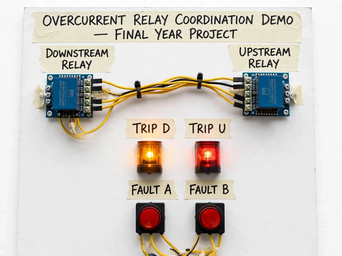
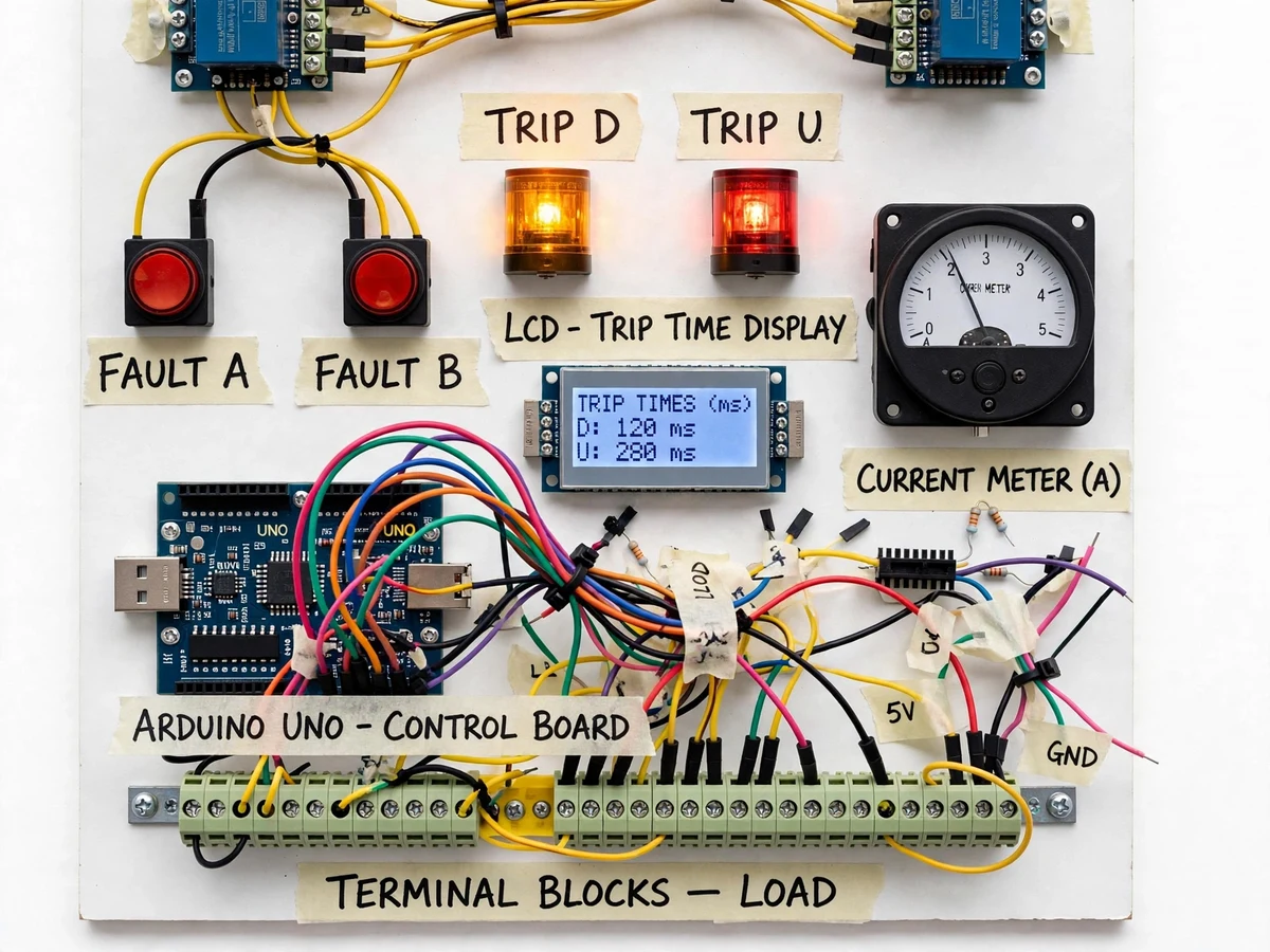
In a real distribution network, a fault should be cleared by the relay closest to it — the downstream relay trips fast while the upstream relay waits as delayed backup, a discipline called grading or coordination. Getting it wrong means a small fault blacks out a whole feeder, yet students usually learn this only as formulas in a textbook, never seeing selectivity happen. Real relay test sets that could demonstrate it cost far more than a college lab can justify. This project closes that gap: a bench panel with two inverse-time overcurrent relay stages wired in series, each following a standard-inverse IDMT characteristic, with fault injection at two points. Press FAULT A and the downstream stage trips in about a hundred milliseconds while the upstream stage starts timing but resets — press FAULT B and the delayed upstream stage clears it instead. An LCD shows both trip times after every test, turning the abstract grading margin into a visible number.
How it works
- The panel is powered from a 12 V DC adapter; a lamp load bank draws a steady healthy-load current, shown on the analog ammeter.
- Pressing FAULT A switches a low-resistance lamp path into the downstream zone, raising the sensed current in both zones above pickup.
- The controller samples both zone currents with hall-effect sensors and evaluates the IEC standard-inverse operating time for each stage from its configured TMS and pickup setting.
- The downstream stage, set with the lower TMS, reaches its operating time first (typically ~120 ms at default settings), opens its trip relay, lights TRIP D, and latches the time on the LCD — the fault current stops.
- The upstream stage had started timing too, but the fault clears before its longer operating time (~280 ms) elapses, so it resets without tripping — selectivity demonstrated.
- Pressing FAULT B injects the fault in the upstream zone, beyond the downstream stage's reach: only the upstream stage times out and trips, lighting TRIP U, acting as backup protection.
- The LCD holds both trip times for comparison against the calculated grading margin, and a panel RESET button arms the panel for the next test.
Tech stack:
- Arduino Uno (ATmega328P) control board
- ACS712 hall-effect current sensor modules
- 12 V DC lamp load banks (simulated healthy + fault loads)
- 16x2 LCD display (trip-time readout)
- Relay modules for trip outputs
- Pushbuttons, indicator lamps, terminal blocks
- 12 V DC adapter with 5 V on-board regulation
| Parameter | Value |
|---|---|
| Control supply | 12 V DC, approximately 2 A (adapter included) |
| Logic supply | 5 V regulated on-board |
| Relay characteristic | IEC 60255-151 standard inverse (IDMT), firmware — design value |
| TMS range | 0.1–1.0 per stage, configurable via presets |
| Pickup setting | Adjustable via potentiometer, marked on panel |
| Fault current | Lamp-load current, approximately 0.5–3 A (design target) |
| Trip-time readout | LCD, 1 ms resolution, latched per test |
| Grading margin | Approximately 150 ms between stages at default settings (design target) |
| Metering | Analog current meter, 0–5 A |
| Panel size | Approximately 45 x 35 cm (expected) |
Project features
- [Two inverse-time relay stages] Downstream and upstream stages each implement the IEC 60255-151 standard-inverse IDMT curve in firmware, computed from live current samples — the same curve family used on real feeders.
- [Fault injection at two points] FAULT A and FAULT B pushbuttons switch a low-resistance lamp path into the downstream and upstream zones respectively, so each protection zone can be faulted independently.
- [Visible selectivity] A downstream-zone fault trips the fast stage while the upstream stage starts but resets when the fault clears; an upstream-zone fault trips the delayed upstream stage — coordination you can watch.
- [Configurable TMS and pickup] Time-multiplier setting (0.1–1.0) and pickup current are set per stage with preset potentiometers, so the student can re-grade the two stages and re-run the demonstration with new margins.
- [Trip-time display] After every test the LCD shows each stage's detection-to-trip time in milliseconds, so the actual grading margin is read straight off the panel.
- [Panel instrumentation] Separate amber TRIP D and red TRIP U indicator lamps plus an analog current meter showing the fault current during each test complete the mimic.
- [ELV safe construction] The whole rig runs on 5 V/12 V DC with lamp banks as the fault load — no mains anywhere in the demonstration circuit, safe for classroom use.
What is included
- Wired demonstration panel: two relay stages, fault pushbuttons, trip lamps, LCD, current meter, terminal blocks
- Arduino firmware implementing the IDMT curves, TMS/pickup handling and trip-time display
- Circuit diagram and wiring schedule
- Grading calculation worksheet (IEC curve worked example with the default settings)
- Commissioning and fault-injection test procedure
- Project report PDF (protection theory, coordination principles, methodology)
- PPT presentation for final review
- Viva Q&A preparation document (IDMT curves, TMS, pickup, grading margin, selectivity)
Limitations & prerequisites
- ELV demonstration only: the panel runs entirely on 12 V/5 V DC and must never be connected to mains — it demonstrates protection logic, not real feeder protection.
- The relay stages are firmware IDMT implementations on a microcontroller, not utility-grade numerical relays; trip times are indicative, not certified to IEC test tolerances.
- Fault currents are lamp-load currents of a few amps; the timing behaviour is illustrative rather than representative of real fault levels.
- Single-phase demonstration only — three-phase coordination, earth-fault and directional elements are out of scope.
- LCD trip times depend on the configured TMS/pickup and the actual load; they are latched per test, not calibrated constants.
- Timing accuracy is limited by the microcontroller's millisecond timer and sensor bandwidth — adequate for a teaching demo, not for protection relay testing.
Frequently Asked Questions
What is relay coordination?
Coordination (grading) means the relay nearest a fault trips first while upstream relays wait as backup. On this panel, a downstream-zone fault trips the fast downstream stage in ~120 ms while the upstream stage starts but resets; an upstream-zone fault trips the delayed upstream stage. The LCD shows both times so the grading margin is visible.
What is TMS and how is it set here?
The time multiplier setting scales the IDMT curve: a lower TMS means a faster trip for the same fault current. Each stage has a preset potentiometer for TMS (0.1–1.0) and one for pickup, so you can re-grade the stages and re-run the fault tests with new margins.
How do the two fault points differ?
FAULT A injects the fault in the downstream zone, which both stages see — the downstream one must win. FAULT B injects it in the upstream zone beyond the downstream stage, so only the delayed upstream stage responds, demonstrating backup protection.
Is the panel safe to demonstrate in class?
Yes. Everything runs on 12 V/5 V DC with lamp loads — extra-low voltage, no mains connection anywhere in the demonstration circuit. The only precaution is normal handling of a powered electronics board.
Is this project suitable for a final-year project?
Yes — for Electrical and EEE programs. It demonstrates protection-system concepts (IDMT curves, TMS, pickup, grading margin, selectivity) with a working bench rig the student can operate and explain in the viva. Suitable for B.E./B.Tech final-year projects in Electrical Engineering.
Components & software requirements
- Arduino Uno (ATmega328P) control board
- ACS712 hall-effect current sensor modules
- 12 V DC lamp load banks (simulated healthy + fault loads)
- 16x2 LCD display (trip-time readout)
- Relay modules for trip outputs
- Pushbuttons, indicator lamps, terminal blocks
- 12 V DC adapter with 5 V on-board regulation
Delivery information
Built-to-order project. Delivery timeline is shared after order confirmation based on current queue.
Support terms
Complete documentation, setup guide, and viva preparation included. Support for setup and explanation provided.