
More project photos (2)
The problem
Solar water heaters turn sunlight into hot water, but a heater without a controller wastes much of that gain. A pump left running all day consumes electricity even when the collector is cold, and a pump switched by hand is rarely turned on when the sun is strong or off when clouds pass. The worst loss happens at night: a pump left running pushes hot water from the tank back up into the cold collector, cooling the stored water instead of heating it. A solar water heater controller solves this with differential-temperature control: it compares the collector temperature with the tank temperature and runs the pump only when the collector is usefully hotter than the tank. This project builds that controller around an Arduino Uno and two DS18B20 sensors, adds a live display, a tank cut-off, and overheat and freeze protection, turning a passive solar heater into a system that heats water only when the sun is actually winning.
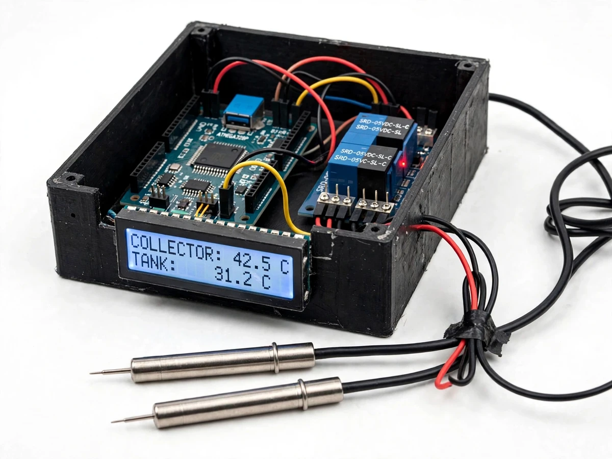
Waterproof DS18B20 probe in a thermowell at the solar collector outlet.
Follow the working sequence
How it works
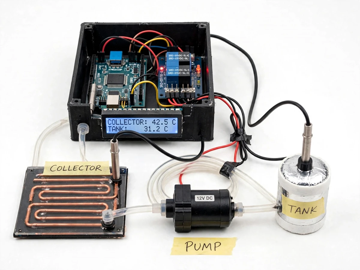
Two waterproof DS18B20 sensors measure the water temperature at the solar collector outlet and inside the storage tank, and the Arduino Uno reads both approximately every 2 seconds. The controller subtracts the tank temperature from the collector temperature: when the collector is at least 8 °C hotter, it switches the circulation pump on through a relay, and when the difference falls to 3 °C or less it switches the pump off, so heat is only moved while the sun is actually winning. Both temperatures and the pump state appear on a 16x2 LCD, and a tank cut-off stops the pump once the stored water reaches the set temperature. If the tank ever approaches the overheat limit the pump stops and a buzzer sounds, and if the collector nears freezing the pump circulates warm tank water briefly to protect the pipes. The whole loop runs on its own from a 12 V supply, with no internet connection needed.
- Two waterproof DS18B20 probes — one in a thermowell at the collector outlet, one at mid-height in the storage tank — report water temperature over a single 1-Wire bus.
- The Arduino Uno reads both sensors approximately every 2 seconds and shows the collector temperature, tank temperature and pump state on the 16x2 LCD.
- Firmware computes the temperature difference (ΔT = collector − tank) and compares it with the configured start and stop setpoints.
- When ΔT reaches 8 °C (design target) the relay energises the 12 V circulation pump; when ΔT falls to 3 °C (design target) the relay drops the pump out, so heat is never pumped backwards from the tank to the collector.
- If the tank reaches the 60 °C cut-off (design target) the pump stops even with a hot collector; above 85 °C (design target) the buzzer sounds the overheat alarm.
- In freezing conditions the controller briefly circulates warm tank water through the collector when the collector sensor falls below 4 °C (design target), protecting the pipes.
Tech stack:
- Arduino Uno (ATmega328P)
- DS18B20 waterproof temperature sensors
- 16x2 LCD display
- 2-channel relay module
- 12 V DC circulation pump
- Arduino IDE · C/C++
- One-Wire sensor bus
- 12 V DC power adapter
| Parameter | Value |
|---|---|
| Controller | Arduino Uno (ATmega328P, 16 MHz clock, datasheet value) |
| Temperature sensors | 2 × DS18B20 waterproof probes (datasheet value: −55 °C to +125 °C range, ±0.5 °C accuracy from −10 °C to +85 °C) |
| Sensor resolution | 12-bit, 0.0625 °C steps (datasheet value) |
| Display | 16 × 2 character LCD showing collector and tank temperatures in °C and pump state |
| Pump control | Differential-temperature switching via 2-channel relay module (datasheet value: 10 A at 250 VAC contacts) |
| Pump | 12 V DC circulation pump, relay-switched (flow matched to tank size at build time) |
| Pump start setpoint | ΔT ≥ 8 °C (design target, adjustable in firmware) |
| Pump stop setpoint | ΔT ≤ 3 °C (design target, adjustable in firmware) |
| Tank cut-off | 60 °C (design target, adjustable in firmware) |
| Overheat alarm | 85 °C tank temperature (design target) |
| Freeze protection | Pump circulates briefly when collector falls below 4 °C (design target) |
| Sensor read interval | Approximately every 2 s (design target) |
| Power supply | 12 V DC adapter, approximately 1 A (design target) |
| Connectivity | None — fully local operation, no internet required |
Project features
The controller's core capability is differential-temperature pump control: it runs the circulation pump only when the collector is hotter than the tank, so every watt of pumping moves heat in the right direction. Second, dual DS18B20 sensing with a live LCD display makes the system transparent — collector temperature, tank temperature and pump state are visible at a glance, which is exactly what a viva examiner wants to see. Third, the safety layer covers both ends of the temperature scale: a tank thermostat cut-off stops heating at the set temperature, overheat protection guards the tank, and freeze protection circulates warm water when the collector nears freezing. Around these three capabilities sit practical touches — manual override, adjustable setpoints and a buzzer alarm — so the build is a complete, demonstrable control system rather than a bare sensor demo.
- [Differential-temperature pump control] The pump runs only when the collector is hotter than the tank by the start setpoint (ΔT ≥ 8 °C, design target) and stops when the difference falls to the stop setpoint (ΔT ≤ 3 °C, design target). The gap between the two setpoints is deliberate hysteresis: on a cloudy day the pump would otherwise chatter on and off every few seconds as the collector temperature wobbles, and that rapid relay cycling is the fastest way to wear out the relay and confuse the demonstration.
- [Dual DS18B20 sensing with LCD display] Two waterproof DS18B20 probes report collector and tank water temperatures on one 1-Wire bus, and a 16x2 LCD shows both readings in °C with the pump state. Builder note from the prototype: the collector probe must sit in a thermowell at the collector outlet and the tank probe at mid-height in the tank — a probe taped to the outside of a pipe reads the pipe temperature, not the water temperature, and the controller then makes decisions on the wrong number.
- [Tank thermostat cut-off] When the stored water reaches the 60 °C cut-off (design target) the pump stops even if the collector is still hot, so the tank is never heated past its set temperature and the pump stops wasting power on water that is already hot enough.
- [Overheat protection with buzzer alarm] If the tank temperature climbs toward the 85 °C overheat limit (design target) — for example on a very hot day with no hot-water use — the pump stops and a buzzer sounds, warning that the system needs attention before pressure or temperature becomes a problem.
- [Freeze protection] When the collector sensor falls below 4 °C (design target) the controller briefly circulates warm water from the tank through the collector, protecting the collector pipes from freezing damage on cold nights without any heater element.
- [Manual / auto mode with push-button override] A push-button toggles between automatic differential control and manual pump control, so the student can run the pump on demand during a demonstration and return to automatic control afterwards without reprogramming.
- [Adjustable setpoints in firmware] The start and stop temperature differences, the tank cut-off and the alarm limits are all constants in the Arduino sketch, so the student can tune the controller to their own collector size and tank volume and explain each value in the viva.
What is included
- Working prototype — controller board, 2 DS18B20 probes, relay module, 12 V circulation pump, 16x2 LCD and demo collector/tank rig
- Arduino firmware source code with adjustable setpoints
- Circuit and wiring documentation
- Component list
- Setup and sensor-calibration instructions
- Project abstract PDF
- Project report, PPT presentation and viva Q&A document
Limitations & prerequisites
- DS18B20 accuracy is ±0.5 °C from −10 °C to +85 °C (datasheet value) — setpoints must allow for that tolerance; control decisions use temperature differences, which partly cancel the error.
- The prototype is a control-system demonstrator at demo scale, not a certified plumbing installation; a real rooftop installation needs a plumber and correctly rated pipework.
- Pump flow rate and pipe sizes must be matched to the actual collector and tank at build time — an oversized pump wastes power and an undersized one under-circulates.
- No cloud logging or remote monitoring in the base build; all readings are local on the LCD.
- Setpoints (8 °C start, 3 °C stop, 60 °C cut-off, 85 °C alarm, 4 °C freeze) are design targets tuned on the demo rig; the student calibrates them on their own collector and tank.
- The relay is electromechanical — the hysteresis gap between start and stop setpoints limits switching cycles, but contact wear remains a long-term factor.
Frequently Asked Questions
Is this project suitable for a final-year project?
Yes — for Electrical, Electronics and Instrumentation programs. It demonstrates sensor interfacing, closed-loop control logic, relay-driven actuation and a real energy-saving application, all of which map directly onto control-systems and applied-electronics coursework. The working prototype gives examiners something measurable to inspect: two live temperature readings, a pump that switches on measured temperature differences, and setpoints the student can explain and adjust.
Which controller is used and why?
An Arduino Uno built around the ATmega328P microcontroller, running at a 16 MHz clock (datasheet value). It has enough digital pins for the 1-Wire sensor bus, the LCD, the relay module, the buzzer and the push-button, and its 5 V logic matches the DS18B20 supply range of 3.0 V to 5.5 V (datasheet value). The choice keeps the build cheap, well documented and easy to explain in a viva.
How does differential-temperature control save energy?
It runs the pump only while the collector is hotter than the tank, so every minute of pumping moves heat into the tank. A pump on a timer or a manual switch runs through cloudy spells and at night, when the collector is cooler than the tank — and then it does worse than waste electricity: it pumps heat out of the tank and into the cold collector. The first-principles rule is simple: the pump must stop the moment the collector is cooler than the tank, or the system heats the sky instead of the water.
What power supply does it need, and does it need internet?
A 12 V DC adapter (approximately 1 A, design target) powers the pump and, through the Arduino's on-board regulator, the controller and display. No internet connection is needed: sensing, control, display and alarms all run locally on the Arduino, so the system works in a lab or on a rooftop with no Wi-Fi at all. An optional Wi-Fi logging module can be added later, but it is not part of the base build.
Can it be fitted to an existing solar water heater?
Yes, if the heater has accessible points to fit the two probes: a thermowell or pocket at the collector outlet and a tapping at mid-height in the tank. The pump is plumbed into the existing circulation loop and the relay switches it in place of a manual switch. Collector and tank sizes vary, so the pump and the setpoints are matched to the installation at build time rather than fixed in advance.
What are the main limitations?
The DS18B20 is accurate to ±0.5 °C from −10 °C to +85 °C (datasheet value), so setpoints must be chosen with that tolerance in mind, and the control decisions use temperature differences, which partly cancel the error. The prototype is a control-system demonstrator at demo scale, not a certified plumbing installation, and the pump size and pipework must be matched to the real collector and tank at build time. There is no cloud logging or remote monitoring in the base build.
Components & software requirements
- Arduino Uno (ATmega328P)
- DS18B20 waterproof temperature sensors
- 16x2 LCD display
- 2-channel relay module
- 12 V DC circulation pump
- Arduino IDE · C/C++
- One-Wire sensor bus
- 12 V DC power adapter
Delivery information
Built-to-order project. Delivery timeline is shared after order confirmation based on current queue.
Support terms
Complete documentation, setup guide, and viva preparation included. Support for setup and explanation provided.
Download free synopsis (PDF)
Enter your name and WhatsApp number — the synopsis PDF downloads immediately. We may send occasional project updates on WhatsApp; no spam.