
More project photos (2)
The problem
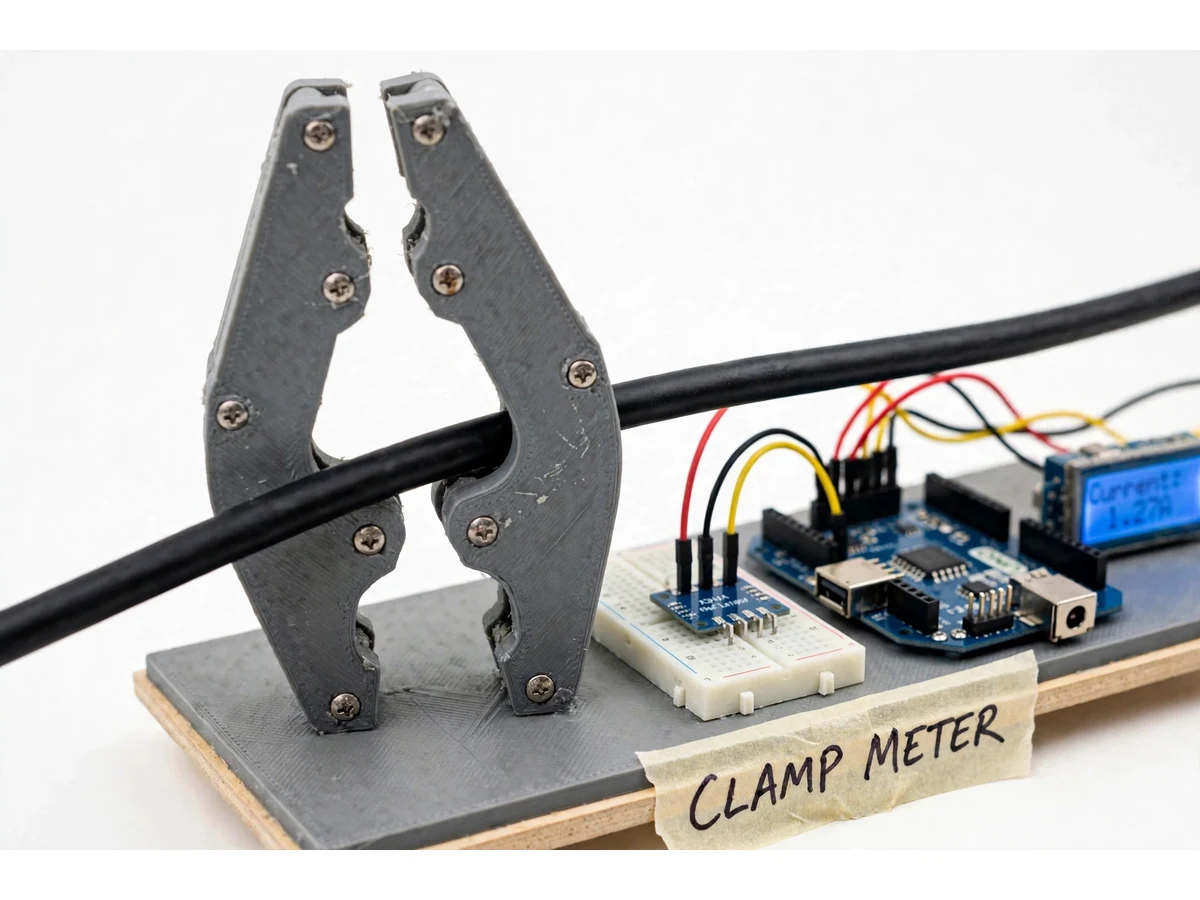
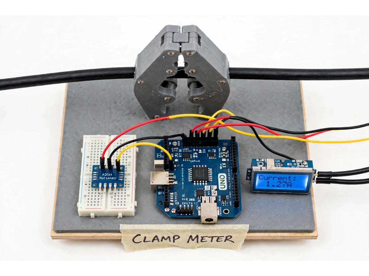
A digital clamp meter using a Hall-effect sensor measures the current flowing in a conductor without cutting the wire or breaking the circuit. The conductor passes through a split ferrite jaw, and the magnetic field circling the conductor is concentrated by the ferrite core across a small air gap, where a linear Hall-effect sensor converts the field strength into a proportional voltage. An Arduino Uno reads that voltage, subtracts the zero-current offset, and converts the result into amperes shown on a 16x2 LCD. Because the Hall effect responds to a steady magnetic field, the same sensor measures direct current directly, while alternating current is measured by sampling the sensor output many times per mains cycle and computing the RMS value in firmware. The build is a compact electrical-measurement prototype that demonstrates magnetic sensing, analogue-to-digital conversion, calibration and RMS mathematics in one instrument students can hold, open and explain.
Ordinary multimeters measure current only in series, which means breaking the circuit, inserting the meter and risking a blown fuse or a disturbed connection. A clamp meter avoids all of that: the jaw closes around a single live conductor and reads the current from its magnetic field, so a running load can be checked without switching anything off. Students study this principle in electrical measurement theory but rarely build the instrument themselves, so the sensing chain — field, core, Hall sensor, ADC, calibration — stays abstract. This project closes that gap with a working prototype that measures both AC and DC, forces the builder to confront real issues such as zero offset, core air-gap sensitivity and stray magnetic fields, and produces a demonstrable instrument for the lab bench.
Current in a single conductor produces a circular magnetic field around it.
Follow the working sequence
How it works
The digital clamp meter works as a chain that starts at the conductor and ends at the display. The split ferrite jaw closes around a single conductor, and the current in that conductor produces a circular magnetic field that the ferrite core concentrates across a small air gap. A linear Hall-effect sensor sitting in that gap converts the field strength into a proportional analogue voltage, so a larger current produces a larger voltage swing around the sensor's resting output. The Arduino Uno reads this voltage with its 10-bit ADC, subtracts the zero-offset value stored during calibration, and applies a calibration factor to convert volts into amperes. For direct current the converted value is the reading itself; for alternating current the firmware samples the sensor output many times across each mains cycle and computes the RMS value. The result is shown on the 16x2 LCD with the AC or DC mode, refreshed approximately 2 times per second (design target).
- The split ferrite clamp jaw is opened, placed around a single conductor of the load circuit, and closed fully so the core faces meet with a minimal air gap.
- Current in the conductor produces a circular magnetic field, which the ferrite core concentrates across the small air gap in the jaw.
- The SS49E linear Hall-effect sensor in the air gap converts the field strength into an analogue voltage that moves above or below its 2.5 V resting output (datasheet value at 5 V supply).
- The Arduino Uno reads the sensor voltage on a 10-bit ADC input, giving approximately 4.88 mV per ADC count (calculated value).
- Firmware subtracts the zero-offset value stored when the calibration button was pressed with the jaw closed and no conductor inside.
- In DC mode the corrected voltage is scaled by the calibration factor into amperes; in AC mode approximately 100 samples per mains cycle (design target) are collected and the RMS value is computed.
- The result is shown on the 16x2 LCD in amperes with the AC or DC mode, and an over-range warning appears if the 10 A design range is exceeded.
Tech stack:
- Arduino Uno (ATmega328P)
- SS49E linear Hall-effect sensor
- Split ferrite clamp jaw
- 16x2 LCD display
- Arduino IDE · C/C++ firmware
- Breadboard · jumper wiring
- 9 V battery · 5 V regulated supply
| Parameter | Value |
|---|---|
| Controller | Arduino Uno (ATmega328P, 16 MHz clock) |
| Hall sensor | SS49E linear Hall-effect sensor (TO-92 package) |
| Sensor sensitivity | 1.4 mV per Gauss (typical, datasheet value at 5 V supply) |
| Sensor null output | 2.5 V at zero magnetic field (datasheet value at 5 V supply) |
| Sensor linear range | ±650 Gauss (typical, datasheet value) |
| Sensor supply voltage | 2.7–6.5 V (datasheet value) |
| ADC resolution | 10-bit, 0–5 V range, approximately 4.88 mV per count (calculated value) |
| Measurement range | 0–10 A AC/DC (design target) |
| Display | 16x2 character LCD with backlight |
| Display refresh | Approximately 2 readings per second (design target) |
| AC sampling | Approximately 100 samples per mains cycle (design target) |
| Jaw opening | Approximately 25 mm conductor clearance (design target) |
| Power supply | 9 V battery with 5 V regulator, or USB 5 V supply |
| Core | Split ferrite clamp jaw with air-gap Hall sensor mounting |
Project features
The digital clamp meter is built around four capabilities that define the whole instrument: non-contact measurement of both AC and DC current from a single conductor, a live digital readout on a 16x2 LCD that shows the value and the AC or DC mode, a one-button zero-offset calibration that removes the sensor's resting voltage before every measurement session, and an RMS calculation in firmware that turns rapid AC samples into a steady RMS reading. Around those four sit the practical details that make the meter usable as a student instrument: an over-range warning when the current exceeds the design range, battery-powered portable operation, and a documented calibration procedure that uses known resistive loads so the student can verify the meter against values worked out by calculation. Together these capabilities make the meter a complete and explainable instrument for the lab bench, rather than a bare sensor demonstration.
- [Non-contact AC and DC current measurement] The split ferrite jaw closes around a single conductor and the Hall-effect sensor reads its magnetic field, so current is measured without breaking the circuit. DC is read directly from the steady field; AC is sampled and converted to an RMS value in firmware.
- [Live LCD current readout with AC/DC mode] A 16x2 LCD shows the measured current in amperes together with the selected AC or DC mode, refreshed approximately 2 times per second (design target), so the reading is visible during a live demonstration.
- [One-button zero-offset calibration] A push-button stores the sensor output with the jaw closed and no conductor inside as the zero point, removing the sensor's resting voltage and small stray-field offsets before each measurement session.
- [RMS calculation for AC waveforms] Firmware takes approximately 100 samples per mains cycle (design target) and computes the root-mean-square value, so an alternating current reads as a steady RMS figure instead of a flickering instantaneous value.
- [Over-range indication] When the measured current exceeds the 10 A design range, the LCD shows an over-range warning instead of a misleading number, teaching the student to respect the instrument's limits.
- [Battery-powered portable operation] The prototype runs from a 9 V battery through a 5 V regulator, so it can be carried to a lab bench or a demo table without a mains adapter for the electronics.
- [Known-load calibration procedure] The build includes a step-by-step procedure for checking the meter against resistive loads of known current, worked out by calculation, so the student can demonstrate and document calibration honestly.
What is included
- Working clamp meter prototype (ferrite jaw, Hall sensor module, Arduino Uno, LCD, battery holder)
- Arduino firmware with AC/DC modes, zero-offset calibration and RMS calculation
- Circuit and wiring documentation with connection diagram
- Step-by-step zero-offset and known-load calibration procedure
- Project report PDF (background, Hall-effect theory, methodology, calibration, results)
- PPT presentation for final review
- Viva Q&A preparation document (Hall effect, RMS, ADC, calibration, clamp-meter safety)
Limitations & prerequisites
- This is an academic prototype meter, not a calibrated or certified measuring instrument — readings are indicative and must not be relied on for safety-critical or billing decisions.
- Accuracy depends on the student's own calibration, on the jaw closing fully, and on the air gap staying clean and consistent; a partly open jaw or dirt in the gap changes the reading.
- Only one conductor may pass through the jaw: clamping a cable carrying both live and neutral together cancels the field and reads near zero.
- Stray magnetic fields from nearby motors, transformers or magnets can shift the reading, which is why zero-offset calibration is done immediately before measuring.
- AC RMS calculation assumes a mains-frequency waveform close to sinusoidal; heavily distorted waveforms will read less accurately.
- The AC demonstration uses a supervised low-current mains test load; the meter must never be clamped onto bare, damaged or exposed conductors.
Frequently Asked Questions
Is this project suitable for a final-year project?
Yes — for Electrical Engineering and Electronics & Telecommunication programs. It demonstrates Hall-effect sensing, magnetic circuit design with a ferrite core, ADC interfacing, RMS mathematics and instrument calibration in a single working meter, and every one of those topics maps directly to standard electrical measurement coursework. The report and viva kit cover the theory behind each stage, so the student can explain the instrument rather than just show it.
How does a Hall-effect sensor measure current without touching the wire?
A current-carrying conductor is always surrounded by a circular magnetic field whose strength is proportional to the current flowing through it. The split ferrite jaw gathers that field and concentrates it across a small air gap, where the linear Hall-effect sensor sits. The sensor produces a voltage proportional to the field strength, so the Arduino can convert that voltage back into amperes. Nothing in the circuit is broken or interrupted, which is the whole point of a clamp meter.
How can one sensor measure both AC and DC?
The Hall effect responds to a magnetic field whether it is steady or changing, so a DC current produces a steady sensor voltage above or below the 2.5 V resting output (datasheet value at 5 V supply), while an AC current makes the sensor voltage swing up and down with the mains cycle. Firmware treats the two differently: DC is a direct conversion after zero-offset subtraction, and AC is sampled approximately 100 times per mains cycle (design target) and reduced to an RMS value.
How is the meter calibrated?
First the zero point is set: with the jaw closed and no conductor inside, the calibration button stores the sensor's resting output as zero. Then the scale is checked against known resistive loads — for example, a 60 W lamp on a 230 V supply draws approximately 0.26 A by calculation (60 ÷ 230), so the meter's reading can be compared with that worked-out value. The procedure is documented step by step, and the student records the comparison in the report rather than claiming a certified accuracy.
Can it measure mains current safely?
The meter itself never touches the conductor, which is the safety advantage of the clamp design, but it is still a student prototype, not a certified instrument. AC demonstrations use a supervised low-current test load with properly insulated cable, and the meter must never be used on bare, damaged or exposed conductors. The demo build keeps all electronics at 5 V, and mains work is done only under faculty supervision with an insulated test rig.
What will I receive with the project?
The working clamp meter prototype with ferrite jaw, Hall sensor module, Arduino Uno, LCD and battery holder, plus the Arduino firmware, wiring documentation, calibration procedure, project report PDF, PPT presentation and viva Q&A document. Everything is built to order, so the firmware, report and presentation are prepared for your specific build and college requirements.
Components & software requirements
- Arduino Uno (ATmega328P)
- SS49E linear Hall-effect sensor
- Split ferrite clamp jaw
- 16x2 LCD display
- Arduino IDE · C/C++ firmware
- Breadboard · jumper wiring
- 9 V battery · 5 V regulated supply
Delivery information
Built-to-order project. Delivery timeline is shared after order confirmation based on current queue.
Support terms
Complete documentation, setup guide, and viva preparation included. Support for setup and explanation provided.
Download free synopsis (PDF)
Enter your name and WhatsApp number — the synopsis PDF downloads immediately. We may send occasional project updates on WhatsApp; no spam.