
More project photos (2)
The problem
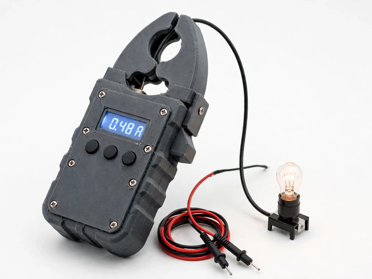
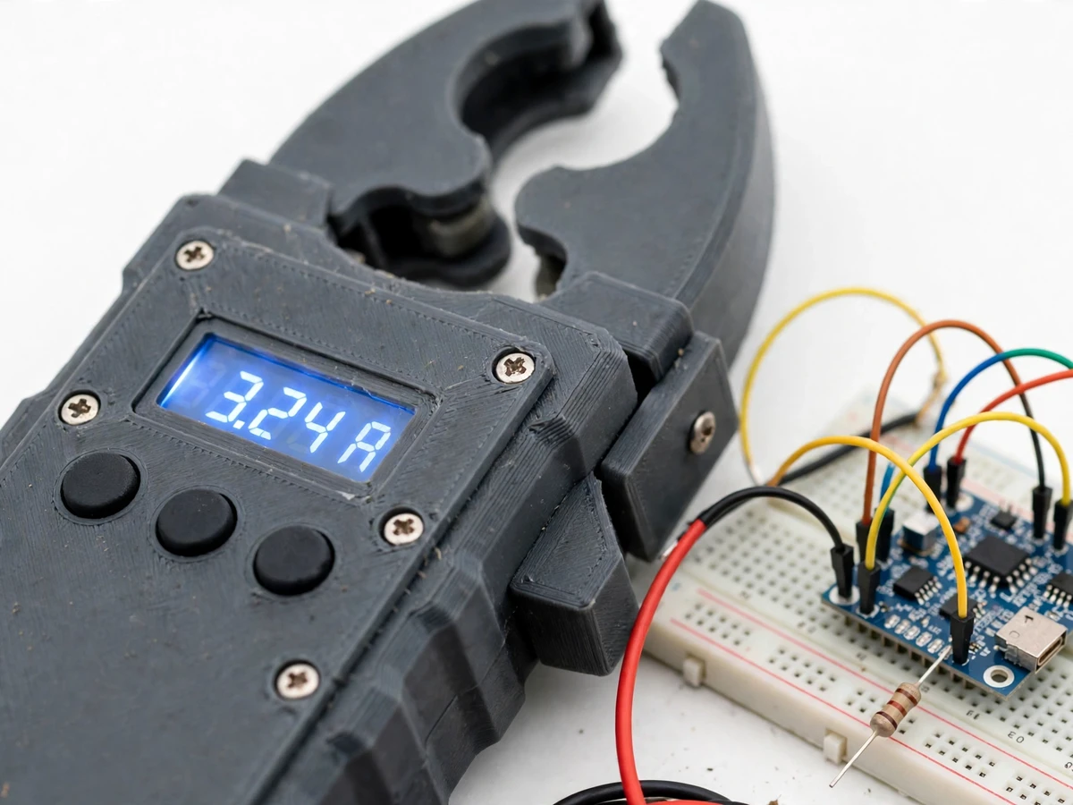
Measuring current the usual way means breaking a circuit and inserting a meter in series, which is inconvenient and, on live wiring, risky for a student. A clamp meter avoids that entirely: its jaws close around one conductor and read the current from the magnetic field around it, with no electrical contact and no cut in the wire. This project builds that instrument from first principles instead of buying one off the shelf. A split-core current transformer sits inside the clamp jaws, a burden resistor turns its small secondary current into a voltage the microcontroller can sample, and firmware computes the True RMS value over whole mains cycles and shows it on an OLED display, automatically choosing the right range. The result is a working meter a student can explain wire by wire: why the clamp must close fully, why it must surround only one conductor, why a burden resistor is needed at all, and why True RMS matters for non-sinusoidal loads.
This is a built-to-order hardware project: the wired prototype, microcontroller firmware, calibration procedure, and the complete viva kit (report, PPT, Q&A) are prepared fresh for you.
The Problem
The Digital Clamp Meter Project with True RMS Measurement and Auto-Ranging answers a practical measurement problem: how do you measure alternating current in a live conductor without breaking the circuit, and how do you get a trustworthy reading when the waveform is not a clean sine wave? A conventional ammeter must be inserted in series, which means cutting or disconnecting a wire, and a basic averaging meter assumes a sine wave and reads low on distorted waveforms from rectifiers, dimmers and switched-mode supplies. The clamp meter built here solves both problems at once. Its split-core current transformer reads current from the magnetic field around a single conductor, so the circuit stays intact, and its firmware samples the waveform and computes the True RMS value, so distorted waveforms are measured by their actual heating value rather than by a sine-wave assumption. Auto-ranging then removes the third student error: picking the wrong range and losing resolution or overloading the display.
That combination is exactly what electrical laboratory work needs. In a lab, students check motor, lamp and rectifier loads, compare expected and measured current, and learn why two meters can disagree on the same load. A shop-bought meter hides all of that inside a sealed case. Building the meter exposes it: the current transformer, the burden resistor, the biasing network, the sampling loop and the RMS calculation are all visible, testable and adjustable. The educational value is in the chain, not just the final number on the display. It also teaches a safety boundary honestly: this is a low-voltage educational prototype for laboratory loads, it is not a certified CAT-rated commercial meter, and it must never be used on mains distribution panels or any circuit beyond its stated laboratory limits.
Carries the alternating current to be measured.
Follow the working sequence
How it works
The Digital Clamp Meter Project with True RMS Measurement and Auto-Ranging works through one continuous chain: clamp, current transformer, burden resistor, sampling, RMS computation and display. The split-core clamp closes around a single conductor, and the alternating current in that conductor produces an alternating magnetic field that links the transformer's core and induces a small proportional current in its secondary winding. That secondary current flows through a burden resistor, which converts it into a small alternating voltage, and a biasing network lifts that voltage so the microcontroller's ADC can read both halves of the waveform. The firmware samples that voltage many times per cycle, removes the measured offset, squares and averages the samples over whole mains cycles, takes the square root for the True RMS current, selects the best range, and writes the result to the OLED display. The whole chain is visible and testable, which is what makes it a strong teaching build.
- The user opens the clamp jaws, places them around one single conductor of the load circuit, and closes the jaws fully until the core faces meet with no air gap.
- The alternating current in the conductor creates an alternating magnetic field, which links the split-core current transformer and induces a proportional secondary current in its winding.
- The secondary current flows through the burden resistor, producing a small alternating voltage proportional to the conductor current.
- A resistor biasing network lifts that alternating voltage to sit centred on half the ADC reference voltage, so the microcontroller can sample both the positive and negative halves of the waveform.
- The microcontroller ADC samples the biased voltage many times per mains cycle, and the firmware subtracts the calibrated zero-current offset from each sample.
- The firmware squares each corrected sample, averages the squares over whole mains cycles, and takes the square root to obtain the True RMS current.
- The firmware compares the RMS value with the range thresholds and selects the smallest range that fits it, with hysteresis to stop flicker at a boundary, then scales the value for that range.
- The OLED display shows the current in amperes with the active range, and the same value, range and any warning flag are sent to the serial monitor for capture.
Tech stack:
- Split-core current transformer clamp
- Arduino Uno
- OLED display module
- Burden resistor · biasing network
- Push buttons for hold and range
- Arduino IDE · C++
- 3D-printed clamp housing
- Rechargeable battery pack
| Parameter | Value |
|---|---|
| Controller | Arduino Uno with ATmega328P microcontroller · 10-bit ADC (datasheet value) |
| Current sensor | Split-core current transformer · 100 A primary to 50 mA secondary (datasheet value) · 2000 turns (datasheet value) |
| Burden resistor | 22 Ω (design calculation) · converts 50 mA secondary current to approximately 1.1 V RMS (design calculation) |
| Biasing | Resistor divider centring the signal at approximately half the ADC reference voltage (design target) |
| Display | OLED display module showing current in A · active range · hold and warning indicators (design target) |
| Measurement | True RMS alternating current computed from sampled waveform data over whole mains cycles (implemented feature) |
| Current ranges | 0 to 2 A · 0 to 20 A · 0 to 100 A (design targets) with hysteresis between ranges (implemented feature) |
| Sampling | Firmware samples across 10 mains cycles per reading · 200 ms per reading at 50 Hz (design calculation) |
| Controls | Hold button · manual range button · calibration button (implemented feature) |
| Warnings | Open-jaw warning · over-range warning on the OLED display (implemented feature) |
| Output | Serial monitor stream of RMS value · active range · warning flags (implemented feature) |
| Power | Rechargeable battery pack for the meter and display (design target) |
| Intended use | Low-voltage educational prototype for laboratory loads only · NOT a certified CAT-rated commercial meter (safety limit) |
Project features
The Digital Clamp Meter Project with True RMS Measurement and Auto-Ranging is built around four capabilities a student can demonstrate live: non-contact current sensing through a split-core current transformer, True RMS computation from sampled waveform data, automatic range selection across three current ranges, and a clear OLED readout with hold and over-range indication. Around those core capabilities, the firmware provides a zero-offset calibration step, an open-jaw warning when the clamp is not fully closed, and a serial output stream that lets the student capture readings for the report. Every feature below is part of the base prototype unless it is marked optional, and voltage and power measurement are deliberately not in the base build: they are listed separately as an optional extension, so nothing is claimed that the prototype does not do.
- [Non-contact clamp sensing] The split-core jaws close around a single conductor and the current transformer inside produces a small secondary current proportional to the conductor current, so the circuit is never broken and the meter never touches the live conductor. Implemented in the base prototype.
- [True RMS computation] The firmware samples the burden-resistor voltage many times per mains cycle, squares each sample, averages over whole mains cycles and takes the square root, giving the True RMS value that reflects the waveform's actual heating effect rather than a sine-wave assumption. Implemented in the base prototype.
- [Auto-ranging] The firmware selects the smallest range that fits the measured current from three design-target ranges, 0 to 2 A, 0 to 20 A and 0 to 100 A, with hysteresis so the display does not flicker between ranges near a boundary. Implemented in the base prototype.
- [OLED live readout] A small OLED display shows the measured current in amperes, the active range and a hold indicator, updating continuously so the student can watch the reading settle as a load switches on. Implemented in the base prototype.
- [Hold and range buttons] Push buttons freeze the displayed reading for noting down, force a manual range for comparison with auto-ranging, and step through the display modes during a demonstration. Implemented in the base prototype.
- [Zero-offset calibration] A calibration step records the no-current ADC offset and subtracts it from every reading, correcting the biasing-network offset so a zero load reads zero rather than a small standing value. Implemented in the base prototype.
- [Open-jaw and over-range warnings] If the clamp jaws are not fully closed, or the measured current exceeds the top range, the display shows a warning instead of a plausible-looking wrong number, so a faulty setup is visible rather than hidden. Implemented in the base prototype.
- [Serial reading output] Every computed RMS value, active range and warning flag is sent to the serial monitor, where readings can be captured and plotted for the report and for comparison against a reference meter. Implemented in the base prototype.
What is included
- Working prototype: split-core clamp meter with current transformer, burden and biasing circuit, Arduino board, OLED display, range buttons and battery pack, wired and tested
- Complete microcontroller firmware for sampling, offset calibration, True RMS computation, auto-ranging, display and serial output
- Circuit and wiring documentation with labelled connections for every wire
- Component list with the exact parts used in the build
- Calibration and demonstration procedure, including the burden-resistor sizing calculation and the single-conductor clamping procedure described below
- Project report PDF (background, current-transformer theory, True RMS theory, methodology, results format, limitations)
- PPT presentation for final review
- Viva Q&A preparation document (current-transformer action, burden resistors, sampling, RMS versus average, auto-ranging, calibration, safety limits)
- Builder note: the burden resistor is sized from the transformer ratio, not guessed — with a 100 A to 50 mA split-core transformer, a 22 Ω burden resistor gives approximately 1.1 V RMS at full-scale secondary current, which keeps the peaked waveform inside the ADC range once biased, and the clamp must close fully around one single conductor only, because an air gap in the core or a second conductor carrying the return current both collapse the reading
Limitations & prerequisites
- This is a low-voltage educational prototype for laboratory loads only: it is NOT a certified CAT-rated commercial meter and must not be used on mains distribution panels, service panels or any high-energy circuit.
- The clamp must close fully around one single conductor: clamping a whole cable with both live and neutral inside cancels the field and reads near zero, and an air gap from dirt or a half-closed jaw reads low.
- True RMS accuracy depends on the current transformer, the burden resistor value, the ADC resolution and the calibration: no accuracy percentage is claimed, and readings must be compared against a reference meter during the demonstration.
- Small currents near the bottom of the lowest range read with poor resolution: currents well below 0.2 A (design note) are indicative only and should not be quoted as precise measurements.
- The base prototype measures alternating current only: voltage, power, frequency and power factor are not measured in the base build and are an optional extension, not an included feature.
- Non-sinusoidal waveforms with very high crest factor, and currents containing a large DC component, fall outside what this single-transformer design is sized for and will read with larger error.
- Battery voltage sag and temperature drift in the burden resistor and biasing network shift the zero offset over a long session, which is why the calibration step must be repeated before a demonstration.
Frequently Asked Questions
How does a clamp meter measure current without touching the wire?
A clamp meter measures alternating current from the magnetic field around a single conductor, without any electrical contact with the wire and without breaking the circuit, because the split-core current transformer inside its jaws links that field and produces a proportional secondary current. The alternating current in a single conductor creates an alternating magnetic field, the split-core current transformer links that field and induces a small proportional secondary current, and the burden resistor and firmware turn that current into a displayed RMS value. Because the circuit is never broken, the load keeps running while it is measured, which is the whole point of the clamp design.
Is this project suitable for a final-year project?
Yes, for Electrical Engineering students, because it demonstrates current-transformer theory, signal conditioning with a burden resistor and biasing network, ADC sampling, True RMS computation, auto-ranging logic and calibration in one working instrument that can be demonstrated live on laboratory loads. The report can compare the prototype's readings against a reference meter on laboratory loads and discuss honestly where the prototype's accuracy falls short of a certified meter.
What is True RMS and why does it matter?
True RMS is the root-mean-square value of a waveform, computed by squaring sampled values, averaging them over whole cycles and taking the square root, and it represents the waveform's actual heating effect regardless of waveshape rather than the value a sine-wave assumption would predict. It matters because a basic averaging meter assumes a sine wave and reads low on distorted waveforms from rectifiers, dimmers and switched-mode supplies, while a True RMS meter measures the real value regardless of waveshape. That difference is easy to demonstrate by measuring a rectifier load with both methods.
Can it also measure voltage and power?
No, not in the base build, because the base prototype measures alternating current only through its clamp transformer and has no voltage-sensing input from which power could be computed, so any voltage or power readout would require an additional isolated sensing stage and a fresh safety review. Voltage and power measurement can be added as an optional extension by adding an isolated voltage-sensing input and computing power from the measured voltage and current together, with the safety limits re-checked for the new input. That extension is quoted separately and is not claimed as part of the base prototype.
Why must the clamp close around only one conductor?
The clamp must close around only one conductor because the magnetic fields of the live and neutral conductors in a cable oppose each other and cancel, so clamping a whole two-core cable reads near zero even when a large current is flowing through it. Clamping a whole two-core cable therefore reads near zero even when a large current is flowing, which looks like a fault but is actually correct physics. The demonstration procedure clamps one conductor only, with the jaws fully closed, and the report explains this as the single most common beginner error with clamp meters.
Is it safe to use on household mains wiring?
No, this prototype must not be used on mains distribution panels or high-energy circuits, because it is an educational prototype without CAT-rated insulation, certification or transient protection for such work, and it is intended only for low-voltage laboratory loads under supervision within the limits stated in the report. It is intended only for low-voltage laboratory loads under supervision, with the load circuit's voltage and current kept inside the limits stated in the report. For any work beyond those laboratory limits, a certified commercial clamp meter must be used instead.
Components & software requirements
- Split-core current transformer clamp
- Arduino Uno
- OLED display module
- Burden resistor · biasing network
- Push buttons for hold and range
- Arduino IDE · C++
- 3D-printed clamp housing
- Rechargeable battery pack
Delivery information
Built-to-order project. Delivery timeline is shared after order confirmation based on current queue.
Support terms
Complete documentation, setup guide, and viva preparation included. Support for setup and explanation provided.
Download free synopsis (PDF)
Enter your name and WhatsApp number — the synopsis PDF downloads immediately. We may send occasional project updates on WhatsApp; no spam.