
More project photos (2)
The problem
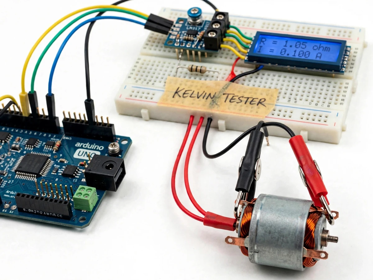
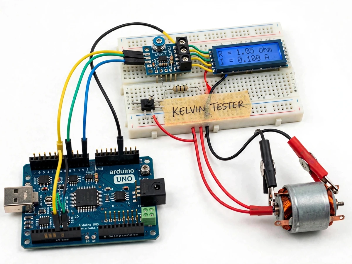
A motor winding resistance tester measures the DC resistance of a motor's copper windings, because a winding that has overheated, shorted between turns, or corroded at a joint changes resistance before the motor fails outright. A normal two-wire multimeter cannot make this measurement honestly: its test leads and probe contacts add their own resistance — typically a few tenths of an ohm — to the reading, and many small-motor windings are only a few ohms themselves, so the lead error can exceed the value being measured. The four-wire Kelvin method solves this with separate force and sense leads: a known current is pushed through the winding on one pair of wires while a second pair measures only the voltage across the winding. This Arduino-based tester applies that method with a constant-current source, a 16-bit ADC and an LCD readout, giving students a repeatable low-ohm measurement that shows why test-lead resistance must be designed out of the measurement.
Winding resistance is one of the first checks in motor maintenance and rewinding work: a rising reading points to a loose or corroded joint, a falling reading points to shorted turns, and an unbalanced reading across three phases points to a winding fault. Students and small workshops usually reach for a multimeter, which quietly reports the leads as well as the winding. This tester makes the error visible and then removes it, so the student learns both the measurement and the reason the textbook method exists. The winding under test must be de-energised and isolated before measurement — the tester never connects to a live motor, a running drive, or any mains supply.
Pushes a steady 100 mA or 10 mA test current through the winding.
Follow the working sequence
How it works
The tester works by forcing a known, steady current through the motor winding and measuring only the voltage that appears across the winding itself. A constant-current source built around an LM317 regulator pushes 100 mA through the winding on the low range, or 10 mA on the high range (design targets), using the outer pair of Kelvin clips. A second, inner pair of sense clips sits as close to the winding as possible and carries almost no current, so by Ohm's law the voltage drop along the sense leads is effectively zero and the measured voltage is the drop across the winding alone. A 16-bit ADS1115 ADC reads that millivolt-level voltage, the Arduino divides it by the known test current to get resistance, applies the stored calibration factor, and shows the result on the 16x2 LCD with the active range.
- Isolate the winding: disconnect the motor from every supply and confirm it is de-energised before any lead is attached.
- Clip the Kelvin leads to the winding terminals on clean, bright copper — force clips on the outside, sense clips on the inside, closest to the winding.
- Select the test range (100 mA for windings under 1 Ω, 10 mA for windings up to 10 Ω — design targets) and press the start button.
- The LM317 constant-current source drives the set current through the force leads and the winding.
- The ADS1115 ADC measures the voltage between the sense leads, which is the drop across the winding alone.
- The Arduino computes resistance as R = V/I, applies the stored calibration factor, and displays the result on the 16x2 LCD with the range and test current.
- The current is switched off, the flyback diode clamps the inductive spike from the winding, and the reading stays on the display until the next test.
Tech stack:
- Arduino Uno (ATmega328P)
- LM317 constant-current source
- ADS1115 16-bit ADC module
- 16x2 LCD with I2C backpack
- Kelvin clips · four-wire test leads
- Arduino IDE · C++
- 1 Ω 1% reference resistor
- 12 V DC power supply
| Parameter | Value |
|---|---|
| Controller | Arduino Uno (ATmega328P, datasheet value) |
| Test current | 100 mA / 10 mA, two ranges (design target) |
| Measurement range | 0.01 Ω – 10 Ω (design target) |
| Display resolution | 0.001 Ω on the low range (design target) |
| Accuracy | ±2% of reading (design target, after calibration) |
| Sense ADC | ADS1115, 16-bit (datasheet value) |
| Display | 16x2 LCD with I2C backpack |
| Test leads | Four-wire Kelvin clips |
| Power supply | 12 V DC, 1 A adapter (expected) |
| Safety rule | De-energised windings only — never test a live or mains-connected winding |
Project features
A motor winding resistance tester built on four-wire Kelvin sensing stands or falls on four capabilities: the Kelvin connection itself, a steady test current, a sensitive voltage measurement, and a readout the student can trust. The force and sense lead pairs keep lead resistance out of the result entirely. An LM317-based constant-current source holds the test current steady at 100 mA or 10 mA (design targets) so the resistance calculation rests on a known current. A 16-bit ADS1115 ADC (datasheet value) resolves the millivolt drop across the winding, and the Arduino computes resistance from Ohm's law and shows it on a 16x2 LCD with the active range. A single-point calibration against a reference resistor and a two-wire comparison mode complete the instrument, letting the student prove the Kelvin advantage on the same winding.
- [Four-wire Kelvin sensing] Separate force and sense lead pairs: the force leads carry the test current while the sense leads measure only the voltage across the winding, so lead and contact resistance never enter the reading.
- [Constant-current source] An LM317-based source holds the test current steady at 100 mA on the low range and 10 mA on the high range (design targets), selected by a switch, so the resistance calculation always uses a known current.
- [16-bit sense measurement] An ADS1115 ADC module (16-bit, datasheet value) reads the millivolt drop across the winding, and the Arduino computes resistance from Ohm's law, R = V/I.
- [LCD readout with range display] A 16x2 LCD shows the measured resistance, the active test current and the selected range, so the reading is unambiguous during a demonstration.
- [Single-point calibration] The tester is calibrated against a 1 Ω 1% reference resistor (datasheet value); the correction factor is stored in the Arduino's EEPROM and applied to every reading.
- [Two-wire vs four-wire comparison mode] The same winding can be measured both ways, so the student can show the lead-resistance error of a two-wire reading and the corrected Kelvin result side by side.
- [Safe test procedure] A push-button starts each test, the winding must be de-energised and isolated first, and a flyback diode across the winding clamps the inductive spike when the test current stops.
- [Open-lead warning] If a sense lead is loose or disconnected, the LCD shows a warning instead of a number, so a bad connection is never mistaken for a winding fault.
What is included
- Working Arduino-based winding resistance tester prototype with Kelvin clips and LCD
- Arduino firmware (constant-current control, ADS1115 readout, R = V/I calculation, calibration storage)
- Wiring diagram and Kelvin lead-connection guide
- Single-point calibration procedure using the 1 Ω reference resistor
- Project report PDF (Kelvin theory, circuit design, measurement procedure, safety rules)
- Abstract PDF (10-section)
- PPT presentation for final review
- Viva Q&A preparation document (Kelvin sensing, Ohm's law, ADC resolution, calibration, safety)
Timeline
- Built-to-order assembly, calibration and testing typically takes 2–3 weeks after order confirmation (expected timeline, confirmed at quotation).
- The report, PPT and viva kit ship with the prototype.
Support
- Remote guidance for setting up the tester and running the first calibration.
- A walkthrough of the Kelvin measurement principle and the comparison-mode demonstration so the student can present it confidently.
- Viva preparation support covering four-wire sensing, constant-current design, ADC resolution and the safety procedure.
Limitations & prerequisites
- ±2% accuracy is a design target after single-point calibration, stated honestly — the report documents the achieved figure from the reference-resistor check, not a measured claim.
- The winding under test must be de-energised and isolated before measurement; the tester must never be connected to a live motor, a running drive, or any mains supply.
- Contact quality affects the reading: Kelvin clips must grip clean, bright copper, and tarnished or painted terminals must be cleaned before clipping.
- Copper resistance changes by approximately 0.4% per °C (standard value for copper), so readings taken on a hot winding and a cold winding are not directly comparable.
- The 100 mA test current warms very low-ohm windings slightly during long tests (expected) — tests are kept to a few seconds.
- This is an academic measurement prototype, not a calibrated laboratory milliohm meter, and it carries no certification.
- Resistances above the 10 Ω design-target range need a different instrument, and the tester measures DC resistance only, not insulation resistance or inductance.
Frequently Asked Questions
Is this project suitable for a final-year project?
Yes — for Electrical, Electronics and Instrumentation programs. It demonstrates four-wire Kelvin measurement, constant-current source design, precision low-voltage sensing with a 16-bit ADC, Arduino firmware and calibration practice — a complete measurement-instrument build with a clear physics principle, a working prototype and strong viva material. The build is compact enough for one semester, and the two-wire comparison mode gives the student a ready-made demonstration of measurement error.
Why can't a normal multimeter measure a motor winding properly?
Because a multimeter measures with two wires, so the resistance of its own leads and probe contacts — typically a few tenths of an ohm — adds to the reading. Many small-motor windings are only a few ohms, so the lead error can exceed 10% of the value being measured. Four-wire Kelvin sensing separates the current path from the voltage path, so lead and contact resistance never enter the result.
What test current does the tester use, and is it safe for the winding?
The tester uses 100 mA on the low range and 10 mA on the high range (design targets). That is far below a motor's operating current, so it cannot damage a healthy winding, and each test lasts only a few seconds, keeping self-heating negligible. The winding must still be de-energised and isolated before any test, and a flyback diode clamps the inductive spike when the current stops.
How is the tester calibrated?
The tester is calibrated with a single-point check against a 1 Ω 1% reference resistor: it measures the reference, the student enters the marked value, and the Arduino stores the correction factor in EEPROM. Repeating the check before a demonstration confirms the reading is still valid. The ±2% accuracy figure is a design target after this calibration, not a measured claim.
Can it test anything besides motor windings?
Yes — any low resistance inside the 0.01–10 Ω design-target range, such as shunt resistors, cable joints, relay contacts and battery interconnects, provided the part is de-energised and isolated first. Inductive parts need the same flyback protection as a winding, and resistances above the range or insulation resistance need a different instrument.
What power supply does the tester need?
A 12 V DC, 1 A adapter (expected) powers the constant-current source and the Arduino through its onboard regulator, while the LCD and ADC run from the Arduino's 5 V rail. No mains connection is ever made to the winding under test, and the tester works entirely offline with no internet connection.
Components & software requirements
- Arduino Uno (ATmega328P)
- LM317 constant-current source
- ADS1115 16-bit ADC module
- 16x2 LCD with I2C backpack
- Kelvin clips · four-wire test leads
- Arduino IDE · C++
- 1 Ω 1% reference resistor
- 12 V DC power supply
Delivery information
Built-to-order project. Delivery timeline is shared after order confirmation based on current queue.
Support terms
Complete documentation, setup guide, and viva preparation included. Support for setup and explanation provided.
Download free synopsis (PDF)
Enter your name and WhatsApp number — the synopsis PDF downloads immediately. We may send occasional project updates on WhatsApp; no spam.