
More project photos (2)
The problem
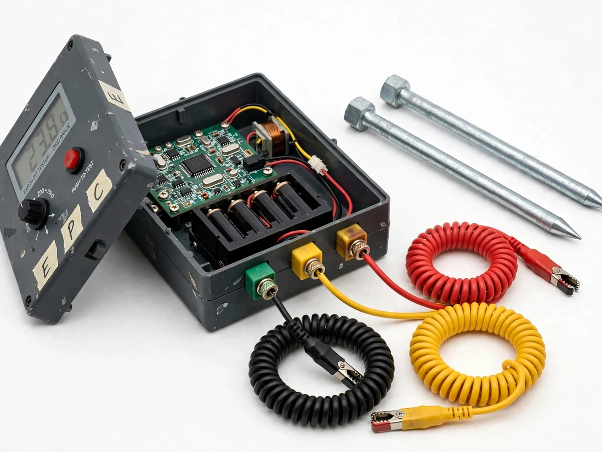
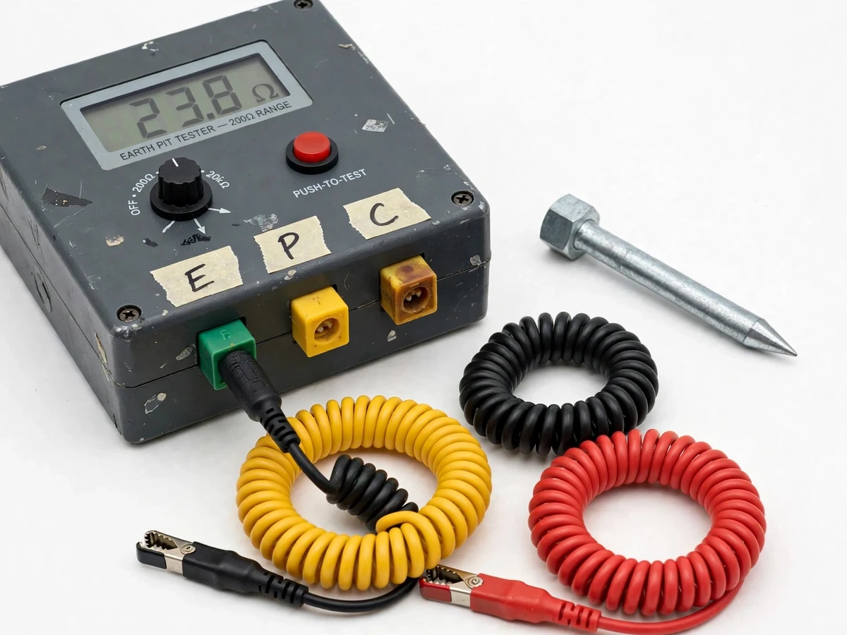
An earth pit resistance tester with digital readout is a portable instrument that measures how well an earth electrode conducts fault current into the soil, using the fall-of-potential method. It injects a small AC test current between the electrode under test and a remote current spike, measures the voltage drop at a potential spike placed at about 62% of the distance, and computes resistance as R = V/I on an onboard microcontroller, displaying the result in ohms on an LCD. Earthing is the silent safety backbone of every electrical installation: a high-resistance earth pit lets fault voltage linger on equipment bodies instead of tripping protection. Yet most students and small contractors still verify earthing by guesswork or by borrowing a commercial earth tester. This project closes that gap with a battery-powered handheld tester built from an Arduino-class microcontroller, a precision ADC and analog signal conditioning — demonstrating AC measurement theory, the 62% rule, and honest instrument design in one build.
Concept
The fall-of-potential method rests on one quotable mechanism: drive a known current into the earth between the electrode under test (E) and a remote current spike (C), then measure the resulting voltage with a second probe (P) placed where the potential curve has flattened — at roughly 62% of the E–C distance. At that point the measured V/I equals the true earth resistance of E, nearly independent of small placement errors. A DC test current would polarize the electrode-soil interface and let stray DC in the ground bias the reading, so this build injects AC at about 128 Hz (design target): far from the 50 Hz mains frequency, letting a narrow band-pass filter reject mains hum and stray pickup. The microcontroller samples the filtered voltage, computes its RMS value, divides by the known test current, and updates the LCD — a complete AC-measurement instrument in a handheld box.
Drives E, P and C spikes; P sits at 62% of the E-C span.
Follow the working sequence
How it works
End to end, the tester works like this: the user disconnects the electrode under test from the installation, drives the current spike into the soil 10–40 m away (design target span), and places the potential spike at 62% of that distance in a straight line, wiring all three to the E, C and P terminals. On push-to-test, the microcontroller switches on a ~128 Hz AC test current of a few milliamps between E and C; the resulting voltage between E and P is picked up, band-pass filtered around the test frequency to reject 50 Hz mains hum, amplified and digitized. Firmware computes the RMS voltage, divides by the known test current to get R = V/I, and shows the resistance on the LCD within about one second (design target). Because the potential spike sits where the potential-gradient curve flattens, small placement errors barely move the reading — the classic reason the 62% rule is trusted in the field.
- Disconnect the electrode under test from the installation (dead test only) and clip the E lead to it; drive the current spike 10–40 m away (design target) in a straight line and connect it to C.
- Place the potential spike at 62% of the E–C distance and connect it to P; in dry soil, pour water around the spikes to improve contact (field practice, approximate).
- Power on and select the range with the rotary knob; the LCD shows the standby screen with battery status.
- Press push-to-test: the unit injects a ~128 Hz AC test current of 2–20 mA (design target) between E and C for about one second.
- The sense channel filters, amplifies and digitizes the E–P voltage; the microcontroller computes RMS and divides by the calibrated test current.
- The LCD displays the earth resistance in ohms with auto-ranging; repeat the reading twice and average for the logbook.
Tech stack:
- Arduino Nano (ATmega328P) — measurement and display firmware in C/C++
- ADS1115 16-bit ADC — sense-channel digitization
- HD44780 16×2 LCD with I2C backpack — digital readout
- LM358 op-amp band-pass filter + gain stage — signal conditioning
- MCU-generated ~128 Hz test tone + RC low-pass — AC excitation source
- 2S 18650 Li-ion pack with TP4056 charger — portable power
- ABS enclosure with E/P/C binding posts — field housing
- KiCad — schematic capture and PCB layout
Requirements
Hardware
- Arduino Nano (ATmega328P), ADS1115 ADC module, 16×2 LCD with I2C backpack
- LM358 dual op-amp, resistors and capacitors for the band-pass filter and gain stage
- 2 × 18650 Li-ion cells, TP4056 charger module, 5 V boost converter
- 3 binding posts (E/P/C), rotary selector switch, push-button, ABS enclosure
- 2 galvanized-steel auxiliary spikes (~30 cm, design target), 3 coiled test leads with crocodile clips
- Digital multimeter (buyer's own) for the calibration check
Software
- Arduino IDE (firmware), KiCad (schematic/PCB), serial terminal for calibration
| Parameter | Value |
|---|---|
| Measurement method | Fall-of-potential, 3-point (E, P, C) |
| Test current | 2–20 mA AC (design target) |
| Test frequency | Approximately 128 Hz (design target) |
| Resistance range | 0.01–2000 Ω (design target) |
| Display | 16×2 character LCD, ohms with auto-range |
| Measurement time | Approximately 1 s per reading (design target) |
| Electrode spacing | E–C span 10–40 m, P at 62% of span (design target) |
| Spike depth | Approximately 0.3–0.5 m (field practice, soil-dependent) |
| Power | 2S 18650 Li-ion pack, approximately 7.4 V nominal |
| Battery life | Approximately 4–6 h of intermittent testing (expected) |
| Accuracy | Approximately ±(3% + 2 digits) vs reference resistors (design target) |
| Enclosure | ABS box, approximately 160 × 110 × 70 mm (design target) |
| Weight | Approximately 0.8 kg with spikes and leads (expected) |
Project features
The Earth Pit Resistance Tester with Digital Readout is built around four capabilities: a true fall-of-potential 3-point measurement that places the potential spike at the 62% point of the E–C span so the reading equals the electrode's real earth resistance; an AC test source at about 128 Hz with narrow band-pass filtering that rejects 50 Hz mains hum and avoids the electrode polarization a DC test current would cause; a direct digital readout covering 0.01 to 2000 Ω (design target) with auto-ranging across three scales; and a portable battery-powered enclosure with E, P and C binding posts, a push-to-test button and coiled test leads with crocodile clips. The firmware samples the filtered sense voltage, computes RMS, divides by the calibrated test current and updates the LCD in about one second. Two galvanized auxiliary spikes and a placement ruler card ship with the unit so a first field test runs without extra shopping.
Implemented features
- [Fall-of-potential 3-point measurement] Implements the classic E–P–C method: current is driven between the electrode under test and a remote current spike while the potential spike samples voltage at the 62% point, so R = V/I gives the true earth resistance.
- [AC test source at ~128 Hz] A microcontroller-generated AC test tone avoids electrode polarization and stray-DC bias; a narrow band-pass stage around the test frequency rejects 50 Hz mains hum before digitization.
- [Digital LCD readout with auto-ranging] A 16×2 LCD shows the resistance in ohms across three auto-selected scales, covering 0.01 to 2000 Ω (design target) without manual range switching.
- [Push-to-test one-second cycle] One button press runs the full cycle — inject, filter, sample, compute RMS, divide by test current, display — completing in about one second (design target).
- [Battery-powered portable enclosure] A 2-cell Li-ion pack in an ABS box with E, P and C binding posts, rotary selector and carry-ready test leads makes the unit genuinely usable away from mains power.
- [Calibrated test current] The test current is set against reference resistors during the build and stored as a firmware constant, with zero-offset compensation measured at every power-on.
- [Complete field kit] Two galvanized auxiliary spikes, three coiled test leads with crocodile clips and a 62%-rule placement card ship with the unit, so the first field measurement needs nothing extra.
Configurable
- Measurement averaging count and LCD backlight timeout are firmware constants the buyer can change and reflash.
Optional customization (not in the base build)
- Data logging to SD card or Bluetooth readout to a phone; 4-point soil-resistivity (Wenner) mode via a firmware and wiring change; serial plot of the potential profile on a laptop.
Future scope (not implemented)
- Clamp-on (stakeless) measurement attachment; GPS-tagged test logging with a companion mobile app.
What is included
- Assembled and tested earth-pit resistance tester unit
- 2 galvanized auxiliary spikes, 3 coiled test leads with crocodile clips
- Spike-placement quick card with the 62% rule diagram
- Firmware source code (Arduino C++) with calibration constants documented
- Circuit schematic and wiring diagram (KiCad/PDF)
- Component list with part numbers and alternates
- Project report PDF (theory, design calculations, build photos, test procedure)
- PPT presentation for final review
- Viva Q&A preparation document (fall-of-potential theory, AC measurement, calibration)
- Project abstract PDF
Timeline
- Week 1–2: circuit design, filter and gain-stage calculations, PCB layout
- Week 3–4: PCB assembly, firmware for test-tone generation and RMS computation
- Week 5: enclosure fitting, terminals, calibration against reference resistors
- Week 6: field trials on 2–3 earth pits, report and documentation finalization
- Approximate build schedule; the actual plan is confirmed at order time.
Support
- Video-call walkthrough of the field test procedure at delivery
- Guidance on viva questions around the 62% rule and AC measurement
- Firmware and document updates for the ordered configuration within the support window
Limitations & prerequisites
- Dead-test only: the electrode under test must be disconnected from the installation; never use on live or energized systems — the unit has no mains connection by design.
- Readings depend on soil moisture: the same pit can read several ohms higher in dry-season soil than after rain; repeat tests across seasons for a stable figure.
- Requires open ground for spike placement (E–C span of 10–40 m, design target); not usable indoors or on concrete without access to remote earth.
- Stray earth currents and nearby buried metal can corrupt readings; the band-pass filter rejects 50 Hz hum but not all interference.
- ±(3% + 2 digits) is a design target verified against a resistor bank, not a calibrated-instrument claim; not a substitute for a certified earth tester for compliance testing.
- Battery runtime of 4–6 h is expected for intermittent testing and drops in cold weather.
Frequently Asked Questions
Why does the tester use AC instead of DC?
Because a DC test current polarizes the electrode-soil interface and stray DC in the ground biases the reading. This unit injects AC at about 128 Hz, where a narrow band-pass filter rejects 50 Hz mains hum, so the measured V/I reflects the true earth resistance rather than electrochemical artifacts.
What is the 62% rule?
In the fall-of-potential method the potential spike P is placed at 62% of the distance between the electrode under test (E) and the current spike (C). At that point the potential-gradient curve flattens, so the V/I reading equals the true earth resistance and small placement errors barely change the result.
How accurate is the reading?
The design target is approximately ±(3% of reading + 2 digits), verified during the build against a calibrated resistor bank. Soil moisture, spike contact and stray currents all affect field readings, so treat the value as an engineering measurement rather than a certified compliance result.
Can it test a live installation's earthing?
No. This is a dead-test instrument: the electrode must be disconnected from the installation before testing. The unit is battery-powered with no mains connection, and it must never be used on energized systems — that restriction is a deliberate safety design choice.
Can soil resistivity (4-point Wenner) measurement be added?
As an optional customization, yes — the same analog front end can drive a 4-spike Wenner array with a firmware change and an extra spike pair. It is not part of the base build, which implements the 3-point fall-of-potential method only, and it is quoted separately at order time.
Is this project suitable for a final-year project?
Yes — for Electrical Engineering and Electronics final-year students. It demonstrates AC measurement theory, analog signal conditioning, microcontroller firmware and a genuine field instrument, with the 62% rule as a strong viva topic. The build, calibration and field-trial documentation map directly onto standard project-review rubrics.
Components & software requirements
- Arduino Nano (ATmega328P) — measurement and display firmware in C/C++
- ADS1115 16-bit ADC — sense-channel digitization
- HD44780 16×2 LCD with I2C backpack — digital readout
- LM358 op-amp band-pass filter + gain stage — signal conditioning
- MCU-generated ~128 Hz test tone + RC low-pass — AC excitation source
- 2S 18650 Li-ion pack with TP4056 charger — portable power
- ABS enclosure with E/P/C binding posts — field housing
- KiCad — schematic capture and PCB layout
Requirements
Hardware
- Arduino Nano (ATmega328P), ADS1115 ADC module, 16×2 LCD with I2C backpack
- LM358 dual op-amp, resistors and capacitors for the band-pass filter and gain stage
- 2 × 18650 Li-ion cells, TP4056 charger module, 5 V boost converter
- 3 binding posts (E/P/C), rotary selector switch, push-button, ABS enclosure
- 2 galvanized-steel auxiliary spikes (~30 cm, design target), 3 coiled test leads with crocodile clips
- Digital multimeter (buyer's own) for the calibration check
Software
- Arduino IDE (firmware), KiCad (schematic/PCB), serial terminal for calibration
Delivery information
Built-to-order project. Delivery timeline is shared after order confirmation based on current queue.
Support terms
Complete documentation, setup guide, and viva preparation included. Support for setup and explanation provided.
Download free synopsis (PDF)
Enter your name and WhatsApp number — the synopsis PDF downloads immediately. We may send occasional project updates on WhatsApp; no spam.