
More project photos (2)
The problem
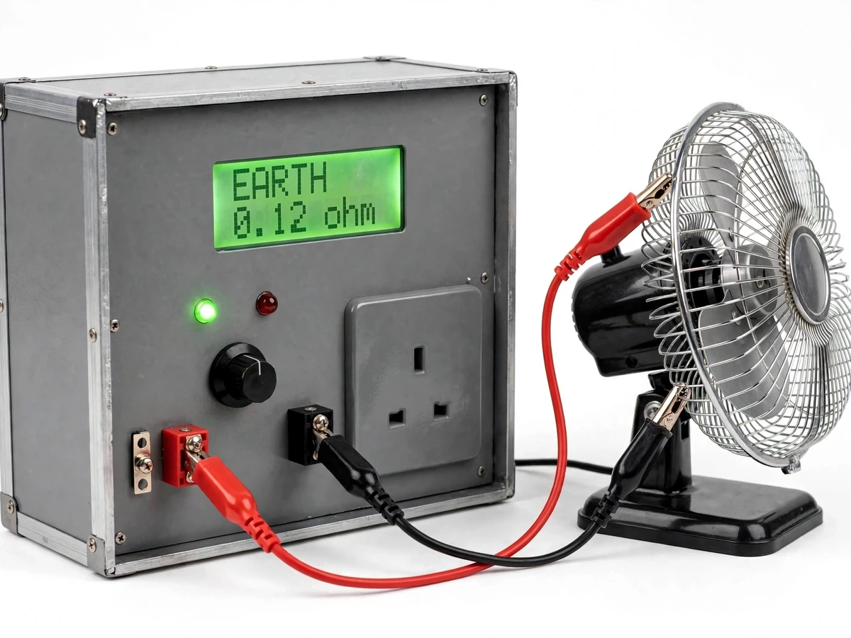
A faulty appliance can look normal and still be dangerous: cracked insulation can leak current to the metal body, and a broken earth wire can leave that body live, so the first sign of trouble is a shock when someone touches it. This project, the Portable Appliance Tester with Insulation Resistance and Earth Continuity Checks, answers that risk with a bench instrument that tests a switched-off appliance before it is ever plugged into the mains. It applies a 500 V DC test voltage to measure insulation resistance, drives a low test current through the earth path to measure continuity resistance, and checks lead wiring and polarity, then shows a clear PASS or FAIL on a 16x2 LCD with green and red LEDs. Built around a microcontroller with relay switching, it is a training and demonstration instrument for learning electrical safety testing, not a certified instrument, and its results must be confirmed with calibrated equipment before any real safety decision.
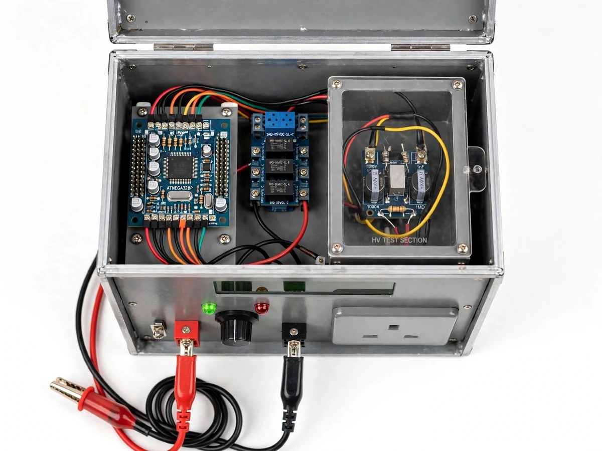
The build is aimed at electrical workshops, maintenance training rooms, and college laboratories, where staff and students need a safe, repeatable way to practise the checks that electricians perform on kettles, fans, irons, power tools, and other plug-in equipment. Because every test runs on a de-energised appliance under microcontroller control, the operator never works with live mains during a test, and the guarded high-voltage section keeps the 500 V DC test circuit physically separated from the low-voltage control board.
How it works
Testing runs as one automatic sequence so the operator never handles a live test voltage. The appliance is switched off and unplugged, its plug goes into the tester's socket, and the test clips go to the exposed metal parts. The microcontroller first checks the leads and plug polarity, then switches in the earth-continuity circuit and measures the resistance of the earth path. Next it switches to the high-voltage section, applies the 500 V DC insulation test between live and neutral joined together and the earth, and computes resistance from the measured leakage current. Each result is compared with its design-target threshold, the LCD shows the measured value in MΩ or Ω, and the green PASS or red FAIL LED lights. The relays then disconnect every test circuit before the appliance is removed.
- The appliance is switched off, unplugged from the mains, and left to cool and discharge; its plug is inserted into the tester's front-panel appliance socket.
- The red and black test clips are attached to the exposed metal parts of the appliance, and the operator presses the start button to begin the automatic sequence.
- The microcontroller first runs the lead and polarity check, verifying the test leads and the plug wiring order, and halts with a FAIL indication if either check fails.
- The relay module switches in the earth-continuity circuit, drives the low test current through the earth path, subtracts the stored lead-zero offset, and displays the resistance in Ω.
- The relays then switch to the guarded high-voltage section, which applies the 500 V DC test voltage, measures the leakage current, and computes insulation resistance, displayed in MΩ.
- The microcontroller compares each result with its design-target threshold, lights the green PASS or red FAIL LED, shows both values on the LCD, and disconnects all test circuits before the appliance is unplugged.
Tech stack:
- ATmega328P microcontroller on an Arduino Nano board
- 500 V DC insulation test module with guarded wiring
- 4-channel relay module for test sequencing
- 16x2 character LCD with green PASS and red FAIL LEDs
- Earth continuity measurement circuit with lead zeroing
- Red and black test leads with crocodile clips
- 12 V DC mains adapter with optional battery pack
- Metal bench enclosure with front-panel appliance socket
| Parameter | Value |
|---|---|
| Insulation test voltage | 500 V DC (design target) |
| Insulation measurement range | 0.1 MΩ to 999 MΩ (design target) |
| Insulation PASS threshold | 1 MΩ or higher (design target, not a certification limit) |
| Earth continuity test current | 200 mA DC (design target) |
| Earth continuity measurement range | 0.01 Ω to 20 Ω (design target) |
| Earth continuity PASS threshold | 0.5 Ω or lower (design target) |
| Display | 16x2 character LCD plus green PASS and red FAIL LEDs |
| Controller and switching | ATmega328P microcontroller (datasheet value: 8-bit AVR, 16 MHz clock) with a 4-channel relay module |
| Power supply | 12 V DC mains adapter rated at 2 A (optional 12 V battery pack add-on) |
| Enclosure size | Approximately 220 mm × 160 mm × 120 mm (design target) |
Project features
The tester brings together four capabilities that matter most in appliance safety checking. First, a 500 V DC insulation-resistance test that finds cracked or damp insulation before an appliance is energised. Second, a low-resistance earth-continuity test that proves the protective earth path is intact. Third, a lead and polarity check that catches miswired plugs and faulty test leads before they corrupt a result. Fourth, automatic relay sequencing with a plain PASS or FAIL display, so the operator follows one safe routine instead of juggling separate meters and test voltages. Around these four, the build adds lead zeroing, guarded high-voltage wiring, mains or battery operation, and a clear single-panel layout that is easy to demonstrate and explain. All eight features below are implemented in the base build; optional add-ons are listed separately under What's included.
- [500 V DC insulation resistance test] The high-voltage section applies a 500 V DC test voltage between the joined live and neutral conductors and the earth, measures the resulting leakage current, and computes insulation resistance, displayed in MΩ on the LCD.
- [Earth continuity test] A low test current is driven through the protective earth path from the plug earth pin to the exposed metal parts, and the resistance is measured and displayed in Ω, so a broken or loose earth shows up as a high reading.
- [Lead and polarity check] Before the main tests, the unit checks the test leads themselves and verifies that the plug wiring order is correct, so a damaged lead or a miswired plug cannot silently produce a false PASS.
- [Automatic relay sequencing] The microcontroller switches the test circuits in a fixed, safe order through a relay module, so the high-voltage section is connected only during the insulation test and is disconnected before the appliance is handled.
- [PASS/FAIL display with measured values] Every result shows both the measured value and a green PASS or red FAIL LED, so the operator sees the number behind the verdict instead of a bare pass light.
- [Lead zeroing] The operator shorts the test leads together and the unit records their resistance, which is then subtracted from continuity readings — essential because lead resistance is comparable in size to the earth resistance being measured.
- [Guarded high-voltage section] The 500 V DC circuit sits behind its own guard cover with clearance from the low-voltage board, and a warning indicator lights while the insulation test is active.
- [Portable bench unit] The tester is built into a single metal enclosure with a carrying handle, a 3-pin appliance socket on the front panel, and red and black test leads with crocodile clips, so it can move between benches and demonstration tables.
What is included
- Assembled portable appliance tester unit in a metal bench enclosure
- Red and black test leads with crocodile clips
- Front-panel 3-pin appliance socket and test terminals
- Complete project report PDF (background, circuit theory, methodology, test procedure, results)
- Wiring diagrams and component layout for the control board and guarded high-voltage section
- Demonstration guide with a step-by-step test routine and sample readings
- PPT presentation for final review
- Viva Q&A preparation document (insulation testing, earth continuity, relay sequencing, electrical safety)
- Data-logging add-on with result storage (optional add-on, not in the base build)
- Rechargeable 12 V battery pack for field demonstrations (optional add-on, not in the base build)
Limitations & prerequisites
- This is a training and demonstration instrument, not a certified portable appliance tester: it does not certify any appliance as safe for use, and real safety decisions must be confirmed with calibrated equipment.
- The unit tests de-energised appliances only; it must never be connected to an appliance that is plugged into the mains or switched on.
- The 1 MΩ insulation threshold and the 0.5 Ω earth-continuity threshold are design targets chosen for this teaching build, not certification limits from any standard.
- Measurement accuracy is not calibrated against a reference standard, so readings are indicative and suitable for teaching and demonstration, not for compliance records.
- The earth-continuity test applies only to earthed appliances with a 3-pin plug; double-insulated appliances have no earth path, so that test does not apply to them.
- The guarded high-voltage section still carries 500 V DC during the insulation test, so the enclosure must stay closed and the unit must be used under supervision while testing.
Frequently Asked Questions
What does this tester actually check?
It checks three things on a switched-off appliance: whether its insulation still blocks leakage current, whether its protective earth path is intact, and whether its plug leads are wired correctly. The insulation test applies 500 V DC and measures resistance in MΩ, the earth test drives a low current through the earth path and measures resistance in Ω, and the polarity check verifies the plug wiring order.
Is this a certified portable appliance tester?
No, it is a training and demonstration instrument built for learning electrical safety testing, not a certified instrument and not a calibration-lab device. Its thresholds are design targets, its readings are not calibrated against a reference standard, and it must never be used to certify an appliance as safe for use. Any real safety decision about an appliance in service must be confirmed with calibrated, certified test equipment.
Why must the appliance be switched off and unplugged?
Because the tester applies its own controlled test voltages and currents, and mains voltage present at the same time would corrupt every reading and create a shock hazard. Testing a de-energised appliance also lets the microcontroller sequence the tests safely through relays, with the high-voltage section connected only during the insulation test and disconnected before the appliance is handled again.
Why does the tester zero its leads before the continuity test?
Because the test leads themselves have resistance, and that resistance is comparable in size to the small earth resistance being measured, so an uncorrected reading would overstate the earth resistance. Builder note from this design: shorting the leads first and subtracting their measured resistance from the result keeps the earth reading honest, and the same first-principles reason is why low-resistance measurement separates the current path from the voltage sensing path.
What does a FAIL result mean for the appliance?
A FAIL means the appliance did not meet the tester's design-target threshold on at least one test and should not return to service on this evidence alone. The LCD shows which test failed and the measured value, so the fault can be traced — for example, low insulation resistance points to damaged or damp insulation, while high earth resistance points to a broken or loose earth connection.
Is this project suitable for a final-year project?
Yes, for Electrical and Electronics Engineering programs, because it combines power-electronics safety concepts, microcontroller programming, relay control, analogue measurement, and high-voltage design practice in one working instrument. The report and demonstration guide cover insulation theory, earth protection, and the honest limits of an uncertified teaching tester, which gives a strong, defensible discussion for review.
Components & software requirements
- ATmega328P microcontroller on an Arduino Nano board
- 500 V DC insulation test module with guarded wiring
- 4-channel relay module for test sequencing
- 16x2 character LCD with green PASS and red FAIL LEDs
- Earth continuity measurement circuit with lead zeroing
- Red and black test leads with crocodile clips
- 12 V DC mains adapter with optional battery pack
- Metal bench enclosure with front-panel appliance socket
Delivery information
Built-to-order project. Delivery timeline is shared after order confirmation based on current queue.
Support terms
Complete documentation, setup guide, and viva preparation included. Support for setup and explanation provided.
Download free synopsis (PDF)
Enter your name and WhatsApp number — the synopsis PDF downloads immediately. We may send occasional project updates on WhatsApp; no spam.