
More project photos (2)
The problem
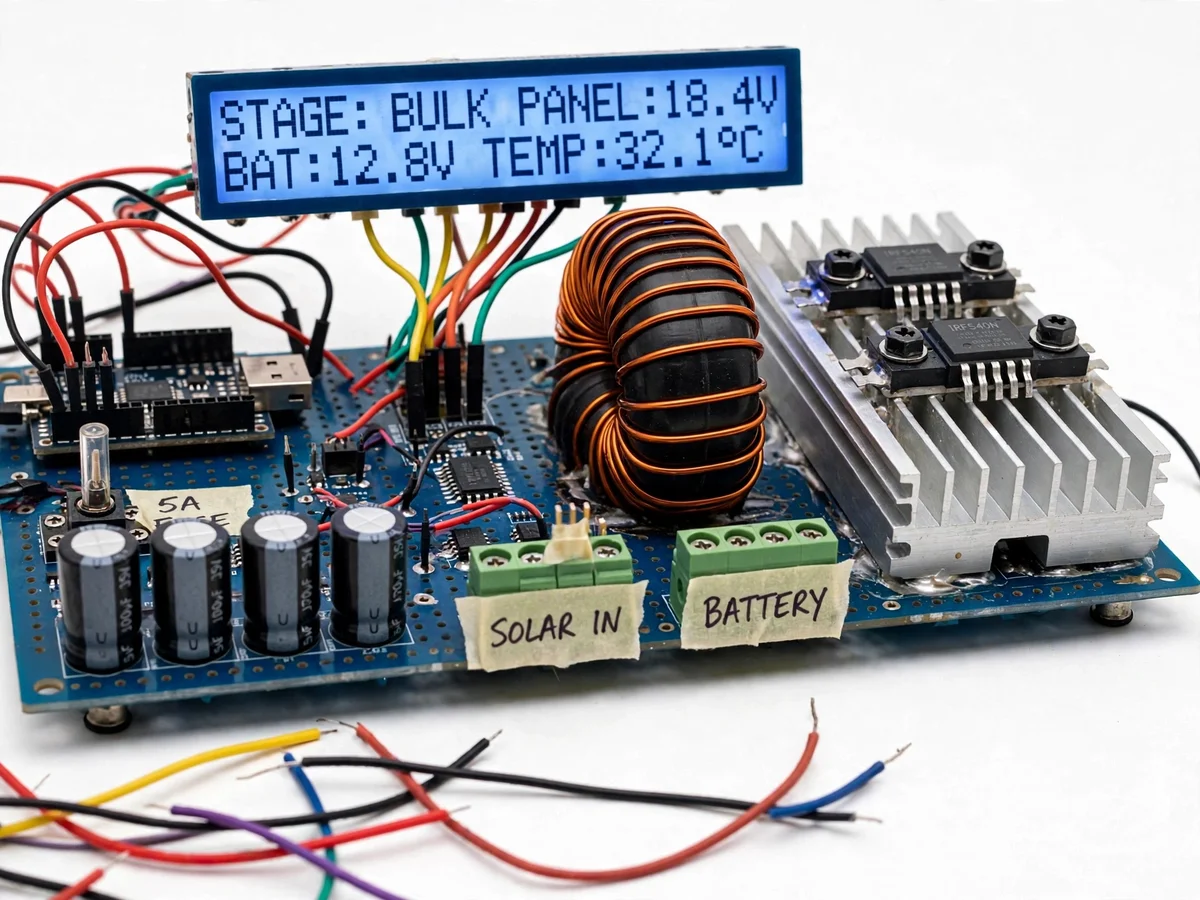
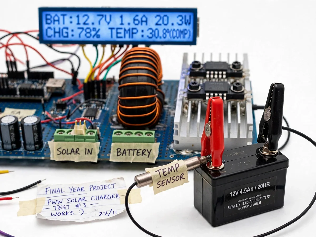
Solar panels connected straight to a battery will either undercharge it on cool days or overcharge it on hot ones, and every deep over-discharge shaves months off battery life. Cheap direct-charge wiring ignores all of this: there is no current regulation, no charge-stage management, no compensation for battery temperature, and no protection when the load drains the battery too far. Lead-acid batteries are particularly unforgiving — charge voltage drifts with temperature (about −4 mV/°C per cell), so a fixed setpoint that is correct at 25°C becomes an overcharge setpoint on a 40°C rooftop and an undercharge setpoint in winter. This project builds the regulator that sits between panel and battery: an Arduino-Nano controller switches a power MOSFET with PWM, implements proper bulk–absorption–float charge stages, reads a temperature sensor taped to the battery and compensates all setpoints live, and disconnects the load before over-discharge. A 16x2 LCD keeps every measurement visible, turning the controller into a complete power-electronics and embedded teaching build.
12 V nominal solar panel wired to the SOLAR IN terminals; up to about 21 V open-circuit.
Follow the working sequence
How it works
- The solar panel connects to the SOLAR IN terminal block; the Arduino measures panel voltage and battery voltage through resistor-divider inputs on two ADC channels.
- The DS18B20 taped to the battery reports temperature, and the firmware shifts the bulk/absorption/float setpoints down or up by approximately −4 mV/°C per cell from the 25°C nominal values.
- In bulk stage the MOSFET is driven near full PWM duty so the panel delivers its available current while battery voltage rises toward the compensated absorption setpoint.
- At the absorption setpoint the firmware switches to voltage regulation, holding battery voltage constant while charge current tapers — the LCD shows falling current at steady voltage.
- When current falls below the configured tail threshold the controller drops to float stage, maintaining the battery without overcharging through the rest of the sun hours.
- After sunset the panel voltage collapses; the Schottky diode blocks reverse current, and the load terminal supplies the battery until voltage hits the LVD point, when the load MOSFET disconnects the load.
- The LCD refreshes every second with panel V, battery V, charge A, watts, temperature, charge stage and fault flags (over-temperature, over-voltage, fuse/fault).
Tech stack:
- Arduino Nano (ATmega328P)
- IRFZ44N N-channel MOSFET, PWM-driven
- DS18B20 digital temperature sensor
- 16x2 character LCD (blue backlight)
- ACS712 Hall-effect current sensor
- Schottky blocking diode, 5 A fuse
- 12 V lead-acid battery, 20 W solar panel
- Arduino IDE (embedded C firmware)
| Parameter | Value |
|---|---|
| Panel input | 12 V nominal, up to ~21 V open-circuit (design range) |
| Panel power | Up to 20 W (design target) |
| Battery | 12 V sealed lead-acid, 4.5–7 Ah (design range) |
| Charge current | Up to ~5 A at the fuse rating (design maximum) |
| MOSFET | IRFZ44N, 55 V / 49 A (datasheet), Rds(on) ~17.5 mΩ typ |
| PWM frequency | Approximately 10–20 kHz (configurable in firmware) |
| Absorption setpoint | 14.4 V at 25°C nominal, temperature-compensated |
| Float setpoint | 13.6 V at 25°C nominal, temperature-compensated |
| Temperature coefficient | Approximately −4 mV/°C per cell (design value) |
| LVD disconnect / reconnect | Approximately 11.1 V / 12.2 V (configurable) |
| Current sensing | ACS712 module, ±5 A variant (datasheet range) |
| Display | 16x2 LCD, refreshed ~1 Hz |
Project features
- [PWM charge switching] An IRFZ44N MOSFET switched by Arduino PWM regulates panel-to-battery current through the inductor stage, replacing crude direct connection with controllable, stage-aware charging.
- [3-stage charge profile] Bulk, absorption (nominally 14.4 V at 25°C) and float (nominally 13.6 V at 25°C) stages are implemented in firmware, with configurable voltage and current thresholds.
- [Battery temperature compensation] A DS18B20 sensor taped to the battery feeds live temperature to the firmware, which adjusts all charge setpoints at approximately −4 mV/°C per cell so hot days do not overcharge and cold days do not undercharge.
- [Live LCD status display] The blue-backlit 16x2 LCD shows panel voltage, battery voltage, charge current, power, battery temperature and the active charge stage, plus fault flags.
- [Load low-voltage disconnect] The load output disconnects at approximately 11.1 V and reconnects at approximately 12.2 V (configurable), protecting the battery from deep discharge.
- [Reverse-current and overcurrent protection] A Schottky blocking diode stops night-time battery discharge through the panel, and a 5 A fuse protects the wiring and PCB traces.
- [Configurable setpoints] Charge voltages, stage thresholds and LVD points are editable constants in the firmware, so the student can document a tuning experiment in the report.
What is included
- Working PWM solar charge controller prototype (controller PCB, MOSFET heatsink stage, LCD, sensor)
- 12 V sealed lead-acid battery and DS18B20 temperature sensor with mounting tape
- Arduino Nano firmware source code with commented setpoint constants
- Circuit and wiring documentation with terminal-block wiring diagram
- Buyer-run calibration procedure (voltage-divider trim, current-sensor offset, temperature offset)
- Project report PDF (theory, design calculations, build procedure, testing methodology)
- PPT presentation for final review
- Viva Q&A preparation document (PWM, MOSFET switching, charge stages, temperature compensation)
Advantages
- Proper 3-stage charging in firmware: bulk, absorption (nominally 14.4 V at 25°C) and float (nominally 13.6 V at 25°C), replacing crude direct panel-to-battery connection with stage-aware PWM current regulation through an IRFZ44N MOSFET.
- Live temperature compensation: a DS18B20 sensor taped to the battery shifts all charge setpoints at approximately −4 mV/°C per cell, so hot days don't overcharge (water loss, plate corrosion) and cold days don't undercharge (sulphation) — a genuine electrochemical requirement, not a gimmick.
- The 16x2 LCD keeps every measurement visible — panel voltage, battery voltage, charge current, power, battery temperature, active charge stage and fault flags — turning the controller into a complete power-electronics and embedded teaching build.
- Load low-voltage disconnect (approximately 11.1 V, reconnect at 12.2 V, configurable) protects the battery from deep discharge; a Schottky diode blocks night-time reverse current and a 5 A fuse protects the wiring. Setpoints are named firmware constants, so a tuning experiment is a built-in viva talking point.
Disadvantages
- Rated for a 20 W class 12 V panel and 4.5–7 Ah batteries — larger panels or batteries need a re-rated MOSFET stage and fuse, documented as an upgrade path.
- Charge setpoints are design values the student trims during their own calibration; no charging efficiency is claimed as measured without the buyer-run test procedure.
- An academic build, not weatherproof or grid-certified — not rated for permanent rooftop installation without an enclosure — and voltage-divider calibration drifts with resistor tolerance, so the procedure must be run on the student's own build.
- PWM switching at ~10–20 kHz can produce audible inductor noise at light loads — normal for this topology — and night-time load runtime is limited by battery capacity (roughly 4–5 h for a 1 A load on a 4.5 Ah battery).
Limitations & prerequisites
- Rated for a 20 W class 12 V panel and 4.5–7 Ah batteries — larger panels or batteries need a re-rated MOSFET stage and fuse, documented as an upgrade path.
- Charge setpoints are design values the student trims during their own calibration; no charging efficiency is claimed as measured without the buyer-run test procedure.
- Night-time load runtime depends on battery capacity and load draw — a 1 A load on a 4.5 Ah battery gives roughly 4–5 hours (expected, load-dependent).
- The prototype is an academic build, not a weatherproof or grid-certified controller — it is not rated for rooftop permanent installation without an enclosure.
- Voltage-divider calibration drifts with resistor tolerance; the calibration procedure must be run on the student's own build for accurate readings.
- PWM switching at ~10–20 kHz can produce audible inductor noise at light loads — normal for this topology, noted in the report.
Frequently Asked Questions
Is this project suitable for a final-year project?
Yes — for Electrical and Electronics/E&TC programs. It demonstrates power-electronics switching (MOSFET, inductor, freewheeling paths), embedded firmware control, ADC-based sensing, temperature compensation of electrochemical charge profiles and load protection in one build.
Which controller and switching device are used?
An Arduino Nano (ATmega328P) runs the firmware: PWM output, three analog voltage channels, one-wire temperature input and LCD control. Switching is handled by an IRFZ44N N-channel MOSFET (55 V / 49 A datasheet rating) with a heatsink, driven through a gate-driver stage from the Arduino's PWM pin.
Why does the battery temperature need sensing?
Lead-acid charge voltage shifts with temperature at roughly −4 mV/°C per cell. A fixed 14.4 V absorption setpoint overcharges the battery on hot days (water loss, plate corrosion) and undercharges on cold days (sulphation). The DS18B20 taped to the battery lets the firmware compensate every setpoint live, which is a genuine electrochemical requirement, not a gimmick.
Can the charge voltages be changed for a different battery?
Yes — absorption, float, LVD disconnect and reconnect voltages are named constants at the top of the firmware file. The report documents the standard 12 V lead-acid values and explains how to recompute them for a different capacity or a gel cell, which makes a solid viva discussion.
What happens at night or when the panel is shaded?
When panel voltage falls below battery voltage the Schottky blocking diode stops reverse current into the panel, and charging simply stops. The load continues from the battery until it reaches the low-voltage disconnect point, then the load MOSFET switches it off; charging resumes automatically the next morning.
How do I prove it works during my demo?
The build ships with a buyer-run test procedure: connect the panel, log the LCD readouts through a full charge cycle, verify stage transitions (bulk → absorption → float) and the LVD trip with a multimeter. Your report then presents your own measured readings — never pre-invented numbers. Suitable for B.E./B.Tech final-year projects in Electrical and Electronics Engineering.
Components & software requirements
- Arduino Nano (ATmega328P)
- IRFZ44N N-channel MOSFET, PWM-driven
- DS18B20 digital temperature sensor
- 16x2 character LCD (blue backlight)
- ACS712 Hall-effect current sensor
- Schottky blocking diode, 5 A fuse
- 12 V lead-acid battery, 20 W solar panel
- Arduino IDE (embedded C firmware)
Delivery information
Built-to-order project. Delivery timeline is shared after order confirmation based on current queue.
Support terms
Complete documentation, setup guide, and viva preparation included. Support for setup and explanation provided.
Download free synopsis (PDF)
Enter your name and email — the synopsis PDF downloads immediately. We may send occasional project updates; no spam, unsubscribe anytime.