
More project photos (2)
The problem
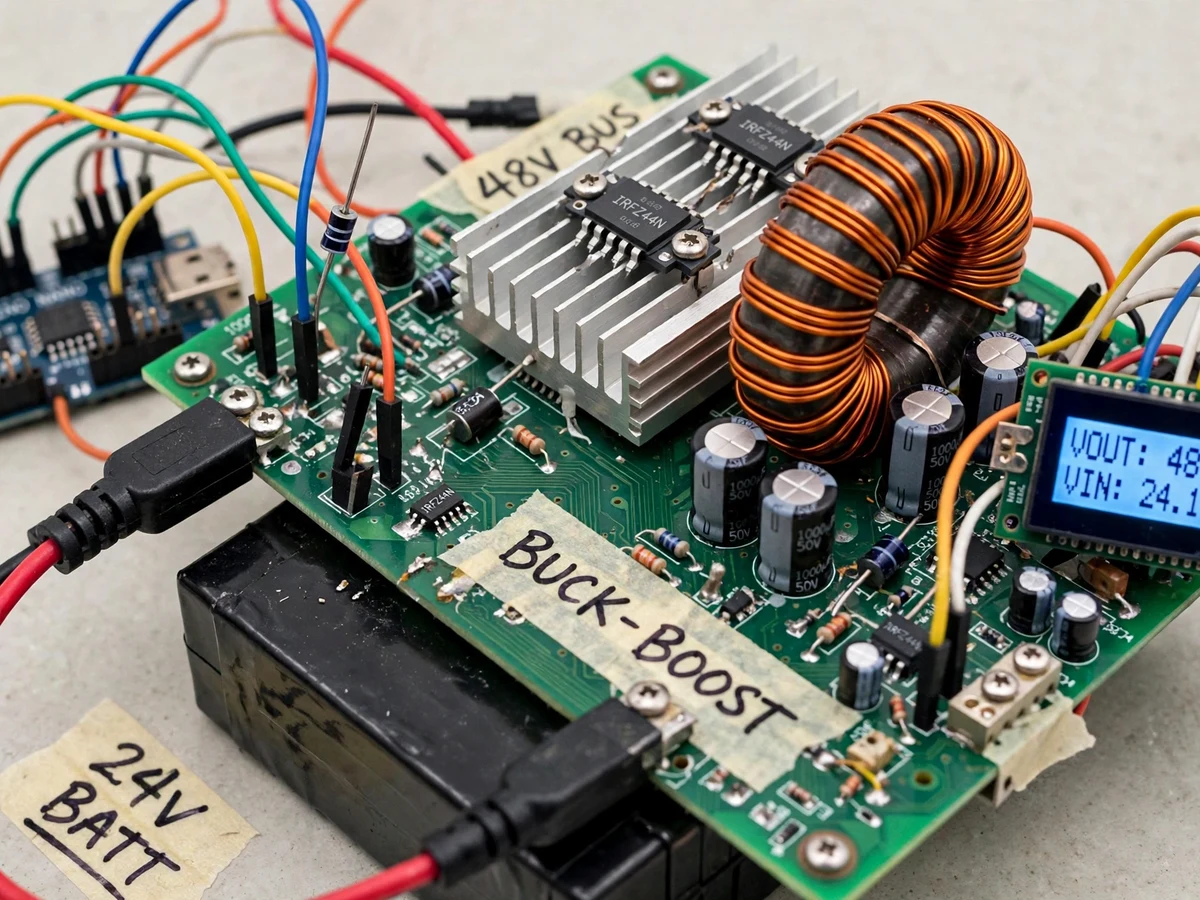
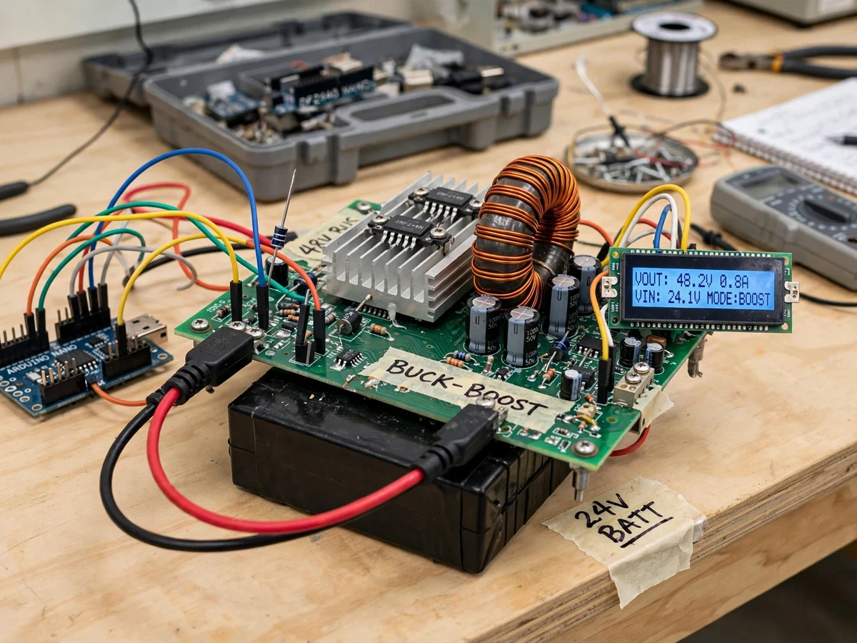
Electric vehicles and small battery energy systems need power to move in both directions: from a higher-voltage DC bus down to a battery during charging, and from the battery back up to the bus during discharge or regenerative support. A single unidirectional charger cannot demonstrate the second direction, and textbook buck and boost circuits are usually studied as two separate experiments. This project combines both directions in one synchronous bidirectional buck-boost stage. A 48 V DC bus and a 24 V battery side share the same MOSFET half-bridge, inductor and controller; only the power-flow direction and duty-cycle control change. The result is a bench-scale rig where charging, discharging, closed-loop regulation and protection can all be observed and measured on one board.
How it works
- In charge mode, the 48 V DC bus feeds the half-bridge; the high-side MOSFET is pulse-width modulated and the inductor current flows into the 24 V battery side, stepping the bus voltage down (buck operation).
- In discharge mode, control reverses: the low-side MOSFET is modulated and the same inductor boosts the 24 V battery voltage back up to feed the 48 V bus.
- Voltage dividers scale the bus and battery voltages into the controller ADC range, and the current-sense stage converts battery current into a proportional voltage for the ADC.
- The firmware compares sensed voltage and current with the configured set-points and adjusts the PWM duty cycle each control cycle to regulate charging voltage or current.
- The gate-driver IC level-shifts the controller PWM into proper high-side and low-side gate signals with dead-time, so the two MOSFETs never conduct at the same instant.
- The LCD updates bus voltage, battery voltage, battery current and mode continuously, while push-buttons switch between CHARGE, DISCHARGE and STOP states.
- If sensed current or battery voltage crosses a protection threshold, the firmware disables PWM, switching stops, and the LCD flags the fault until the rig is reset.
Tech stack:
- Arduino Nano (ATmega328P) PWM controller
- IR2104-class MOSFET gate driver
- N-channel power MOSFETs · synchronous half-bridge
- Toroidal power inductor · buck-boost stage
- Shunt-based current sensing · voltage dividers
- 16x2 character LCD
- Arduino IDE (C/C++ firmware)
- 48 V DC bus · 24 V battery (design targets)
| Parameter | Value |
|---|---|
| DC bus voltage | 48 V DC (design target) |
| Battery-side voltage | 24 V nominal (design target, lead-acid or Li-ion pack with its own BMS) |
| Topology | Synchronous bidirectional buck-boost, single inductor (implemented) |
| Switching frequency | 20 kHz (design target) |
| Inductor | Approximately 100 µH toroidal (design target) |
| Rated power | Approximately 100 W (design target, bench-scale only) |
| Battery current limit | Approximately 4 A (design target, firmware-configurable) |
| Controller | Arduino Nano, ATmega328P (implemented) |
| Display | 16x2 LCD — bus V, battery V, battery A, mode (implemented) |
| Conversion efficiency | Approximately 85–90% (expected, load-dependent, not a measured claim) |
| Isolation | None — non-isolated topology (stated limitation) |
Project features
- [Bidirectional buck-boost power stage] One inductor and one MOSFET half-bridge handle both directions — buck (step-down) charging from the 48 V bus to the 24 V battery and boost (step-up) discharge from the battery back to the bus.
- [Synchronous MOSFET half-bridge] Two N-channel MOSFETs driven by a dedicated gate-driver IC switch complementarily, reducing diode conduction loss compared with a diode-rectified design and demonstrating synchronous rectification.
- [Closed-loop PWM control] The controller adjusts PWM duty cycle from sensed output voltage and current, holding the set charging voltage or current as the battery voltage rises instead of running open-loop.
- [Voltage and current sensing] Resistive dividers sense both port voltages and a shunt-based current sense stage measures battery current, giving the firmware the feedback needed for regulation and protection.
- [LCD readout and mode selection] A 16x2 LCD shows bus voltage, battery voltage, battery current and the active mode (CHARGE or DISCHARGE), selected with push-buttons so both directions can be demonstrated live.
- [Protection cut-offs] Firmware cut-offs stop switching on over-current, battery over-voltage and under-voltage conditions, and a fuse plus reverse-polarity care in wiring protect the bench rig during experiments.
- [Configurable charge parameters] Charging voltage set-point, current limit and mode thresholds are firmware parameters (configurable in code) — they can be retuned for a different 24 V battery pack within the design range; isolated or CAN-based variants are optional customisations, not part of the base build.
What is included
- Working bidirectional converter prototype (power PCB/heatsink assembly, controller board, LCD, battery-side and bus-side terminals)
- Controller firmware / source code with PWM control, sensing and protection logic
- Circuit diagram, wiring documentation and component list
- Setup and operating instructions for charge and discharge demonstrations
- Project report PDF (background, converter theory, design calculations, methodology)
- Project abstract PDF
- PPT presentation for final review
- Viva Q&A preparation document (buck, boost, duty cycle, synchronous rectification, closed-loop control)
Limitations & prerequisites
- Bench-scale only: approximately 100 W design target — this is a teaching prototype, not a charger for a full-size EV traction pack.
- Efficiency is load-dependent (approximately 85–90% expected) and falls at light load and at high current due to MOSFET, inductor and wiring losses; no measured efficiency is claimed.
- The base design is non-isolated: bus and battery share a common ground, so it must not be connected directly to mains or to a vehicle harness.
- Thermal limits apply: MOSFETs and the inductor heat up under sustained load and rely on the fitted heatsink and natural cooling; continuous operation at the current limit needs monitoring.
- Battery chemistry limits apply: charging set-points suit one configured 24 V pack type; Li-ion packs must have their own BMS, and lead-acid and Li-ion profiles are not interchangeable without retuning.
- Not a certified EV charger: there is no automotive qualification, no CAN communication with a vehicle, and no grid or safety certification.
- Regulation accuracy depends on divider and shunt tolerances and ADC resolution; readings are for demonstration and control, not precision metrology.
Frequently Asked Questions
Is this project suitable for a final-year project?
Yes, for Electrical Engineering and Power Electronics programmes. It demonstrates DC-DC converter design, duty-cycle control, synchronous switching, inductor selection, closed-loop feedback and protection in a single build. The design calculations, charge and discharge demonstrations, and honest discussion of losses and thermal limits give strong, concrete material for the report and viva.
Which controller is used and how does the PWM control work?
An Arduino Nano generates the PWM at a 20 kHz design-target switching frequency. It reads bus voltage, battery voltage and battery current through its ADC, compares them with the configured set-points, and adjusts the duty cycle to regulate output. A gate-driver IC converts the logic-level PWM into high-side and low-side MOSFET gate signals with dead-time.
How safe is the converter to operate on a bench?
The firmware stops switching on over-current, battery over-voltage and under-voltage, and the rig uses a fuse, a heatsink and low-voltage DC only — 48 V bus and 24 V battery, never mains. Safety still depends on correct wiring and supervision: the topology is non-isolated, terminals are exposed on a prototype, and it is not a certified charger.
What efficiency should be expected from the converter?
Approximately 85–90% is expected near the useful load range, stated as an expectation and not a measured result. Efficiency drops at very light load, where switching and control losses dominate, and at high current, where conduction losses in the MOSFETs, inductor and wiring rise. The report explains each loss source so measured values from the delivered build can be compared honestly.
Can the converter work with a different battery voltage or a real EV?
The firmware set-points and sensing dividers are configurable for nearby 24 V-class packs, and the design method scales on paper to other voltages. As built, it is a bench prototype of approximately 100 W design target for a 24 V battery and 48 V bus. Charging a real EV traction pack needs far higher power, isolation and certification, which are outside this build.
Components & software requirements
- Arduino Nano (ATmega328P) PWM controller
- IR2104-class MOSFET gate driver
- N-channel power MOSFETs · synchronous half-bridge
- Toroidal power inductor · buck-boost stage
- Shunt-based current sensing · voltage dividers
- 16x2 character LCD
- Arduino IDE (C/C++ firmware)
- 48 V DC bus · 24 V battery (design targets)
Delivery information
Built-to-order project. Delivery timeline is shared after order confirmation based on current queue.
Support terms
Complete documentation, setup guide, and viva preparation included. Support for setup and explanation provided.
Download free synopsis (PDF)
Enter your name and email — the synopsis PDF downloads immediately. We may send occasional project updates; no spam, unsubscribe anytime.