
More project photos (2)
The problem
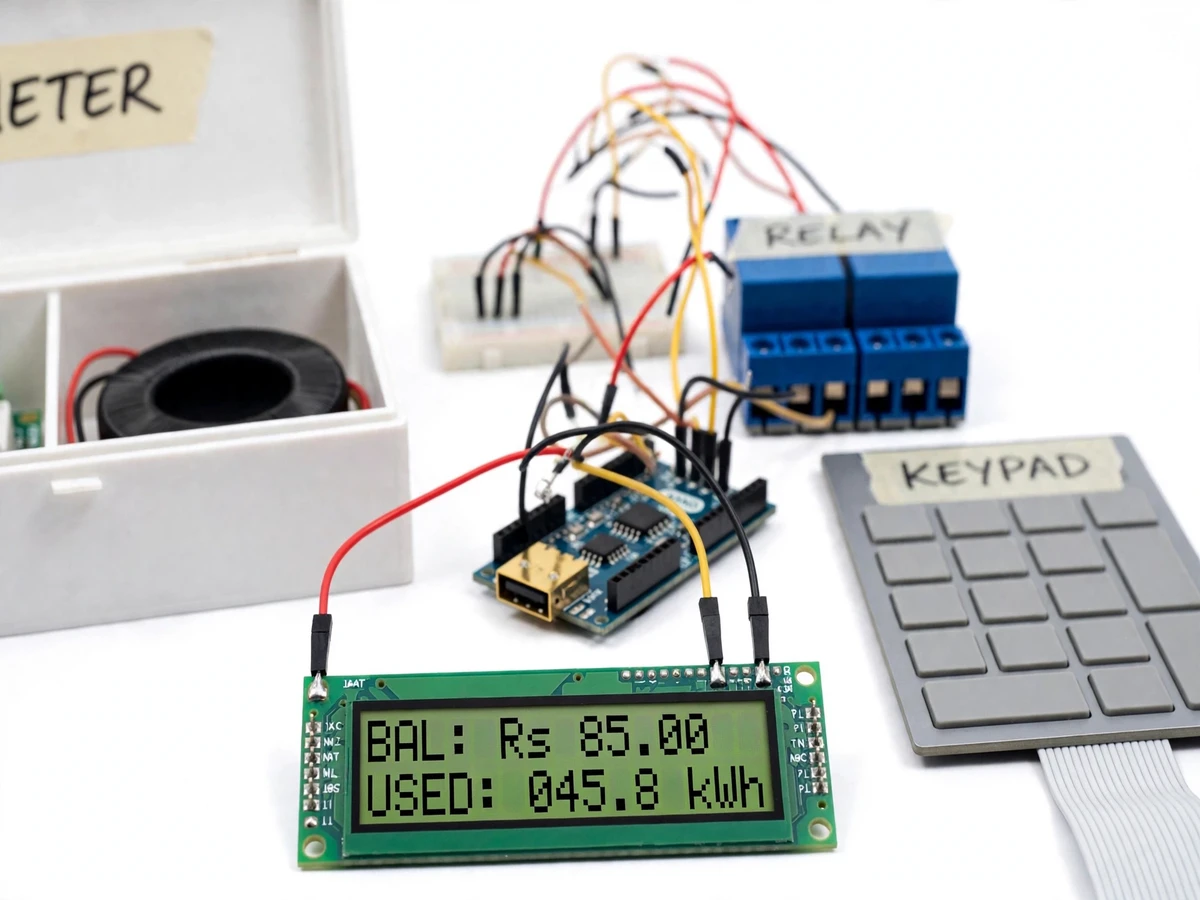
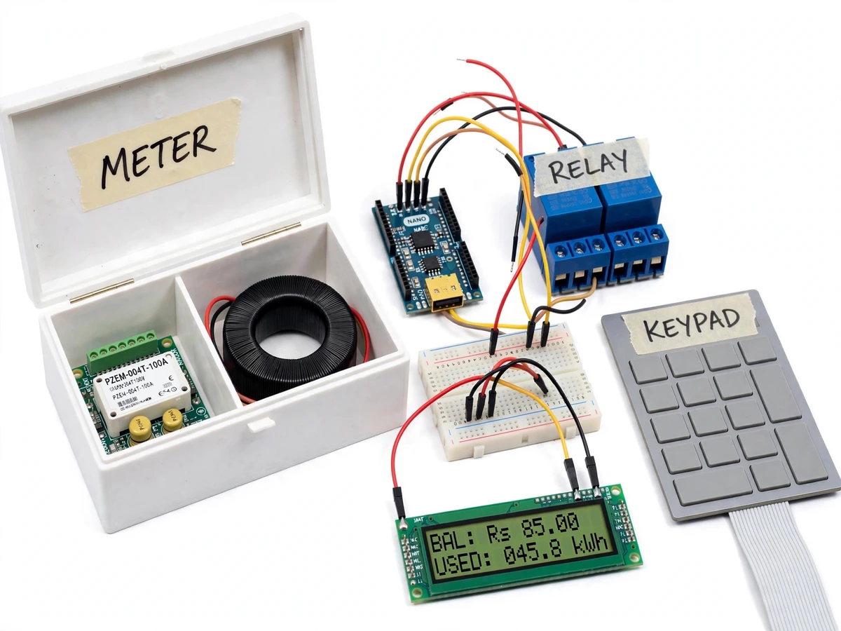
Conventional postpaid meters disconnect payment from consumption: the bill arrives weeks later, and overloads go unnoticed until a breaker trips or wiring overheats. Prepaid metering solves the first problem, and adding a programmable load limit solves the second. This project builds a working single-phase prepaid energy meter: a PZEM-004T energy-metering module measures the actual voltage, current and power drawn by the load, an Arduino Nano maintains the prepaid balance in non-volatile EEPROM, and a relay module switches the consumer supply. Balance is added by typing recharge codes on a 4x4 membrane keypad — exactly like mobile recharge vouchers — and the LCD shows the remaining balance, total energy consumed and the current load at all times. A separate programmable limit watches the instantaneous power: cross it, and the relay disconnects the load with an alarm message. Everything runs on real measured values from the PZEM-004T, not simulated numbers, which makes it a genuinely testable final-year build.
Consumer who recharges credit, acknowledges alarms and uses the load.
Follow the working sequence
How it works
- The mains supply passes through the current-transformer coil of the PZEM-004T, which samples voltage (80–260 V AC) and current every cycle and computes power and energy internally.
- The Arduino Nano polls the PZEM-004T over TTL serial at 9600 baud, typically once per second, and converts the reported energy into monetary deduction at the configured tariff (Rs/unit set through the keypad).
- Each second the controller subtracts the consumed cost from the stored balance, updates total units in EEPROM, and refreshes the LCD with balance, units used and instantaneous watts.
- Recharge codes are entered on the 4x4 keypad; a valid code adds its value to the balance, and the relay closes again if the supply had been cut.
- If the balance reaches zero, the Nano drives the relay module to open the load contactor, and the LCD shows "BALANCE NIL — RECHARGE".
- Independently, if instantaneous power exceeds the programmed load limit for more than the set grace period, the relay opens with an "OVERLOAD" alarm; the supply is restored only after the overload clears and the user acknowledges on the keypad.
Tech stack:
- Arduino Nano (ATmega328P)
- PZEM-004T energy-meter module + current transformer
- 4x4 membrane keypad
- 16x2 LCD with I2C backpack
- 2-channel 5V relay module
- EEPROM (on-chip, ATmega328P)
- Arduino IDE (embedded C++)
- Fritzing-style wiring diagram
| Parameter | Value |
|---|---|
| Supply measured | Single phase, 230 V AC nominal (PZEM-004T range 80–260 V) |
| Current range | 0–100 A via supplied current transformer (datasheet value) |
| Metering resolution | Voltage 0.1 V, current 0.001 A, power 0.1 W, energy 1 Wh (PZEM-004T datasheet) |
| Controller | ATmega328P @ 16 MHz, 1 kB EEPROM (datasheet) |
| Relay contacts | 10 A @ 250 V AC per channel (module datasheet) — prototype load ≤ 1 kW resistive |
| Recharge codes | 6-digit numeric, validated in firmware |
| Balance resolution | Rs 0.01 |
| Metering poll rate | 1 s (configurable in firmware) |
| Load limit | Programmable 50–1000 W via keypad (design parameter) |
| Overload grace period | 3 s (configurable in firmware) |
| Low-balance threshold | Configurable, default Rs 20 (design parameter) |
Project features
- [True energy metering] A PZEM-004T module with a current transformer measures real voltage, current, power and accumulated energy — the same quantities a utility meter bills on.
- [Keypad recharge] Credit is added by entering numeric recharge codes on a 4x4 membrane keypad, with the balance validated and stored in EEPROM so it survives power cuts.
- [Programmable load limit] The allowed maximum power is set through the keypad; exceeding it disconnects the load via the relay and flags an overload on the LCD.
- [Automatic disconnection] The relay drops the consumer supply when the balance reaches zero and restores it on the next valid recharge.
- [Live consumption display] A 16x2 LCD continuously shows remaining balance, energy consumed and instantaneous load for the consumer.
- [Low-balance warning] The LCD flashes a warning and (optionally) a buzzer sounds when the balance falls below a configurable threshold.
- [Non-volatile accounting] Balance and total units are stored in EEPROM on every update cycle, so a power failure never corrupts the account.
- [Calibration procedure] A step-by-step calibration against a known resistive load is included so the build can be verified in the lab.
What is included
- PZEM-004T-100A energy-meter module with current transformer
- Arduino Nano controller, wired and programmed
- 4x4 membrane keypad and 16x2 LCD, wired to the controller
- 2-channel relay module wired for load switching
- Enclosure box with labeled compartments
- Solderless/wired prototype assembly with masking-tape labels
- Firmware source (Arduino C++) with commented tariff, limit and code tables
- Wiring diagram and step-by-step calibration procedure
- Project report PDF (background, metering theory, circuit design, firmware flow, calibration)
- PPT presentation for final review
- Viva Q&A preparation document (energy metering, CT operation, relay isolation, EEPROM wear)
Limitations & prerequisites
- Prototype metering only: it is not a certified utility meter and cannot be used for legal billing — accuracy is bounded by the PZEM-004T datasheet and verified by your own calibration, not by a lab certificate.
- The relay module is rated 10 A per channel; the prototype is demonstrated and warranted only up to a 1 kW resistive load, never full household mains switching.
- Recharge codes are validated locally in firmware (no server, no SMS gateway) — a determined user with the firmware source could regenerate codes; production systems use encrypted tokens.
- The balance and tariff are demo parameters; they do not reflect any actual utility tariff.
- Only single-phase loads are supported; three-phase metering needs additional CTs and a different firmware architecture, listed as future scope.
- The enclosure is a prototype housing, not IP-rated for outdoor installation.
Frequently Asked Questions
How does the meter actually measure energy?
The PZEM-004T samples the voltage and current waveforms many times per AC cycle and computes true power and accumulated energy internally. The Arduino reads these values over serial and converts energy into cost using the tariff you set.
How does keypad recharge work?
You enter a 6-digit code on the keypad. The firmware checks it against its code table, and a valid code adds the corresponding credit to the balance stored in EEPROM. A real utility would use one-time encrypted tokens; this build demonstrates the concept with a local table.
What happens when the balance runs out?
The relay opens and the load is disconnected, exactly like a real prepaid meter. Entering a new recharge code restores the supply immediately.
What is the programmable load limit for?
It caps the instantaneous power a consumer can draw. If the load exceeds the limit for more than the grace period, the relay trips with an overload alarm — the same principle behind sanctioned-load enforcement.
Is the meter accurate enough to trust?
It is as accurate as the PZEM-004T module's datasheet claims, and the included calibration procedure lets you verify it against a known resistive load (e.g. a 100 W bulb) in the lab. It is a prototype, not a certified billing meter.
Is this project suitable for a final-year project?
Yes — for Electrical, Electronics and Instrumentation programs. It covers AC measurement, current transformers, embedded firmware, relay control of mains loads, and a real consumer-facing application with a working recharge workflow. Suitable for B.E./B.Tech final-year projects in Electrical, Electronics and Instrumentation.
Components & software requirements
- Arduino Nano (ATmega328P)
- PZEM-004T energy-meter module + current transformer
- 4x4 membrane keypad
- 16x2 LCD with I2C backpack
- 2-channel 5V relay module
- EEPROM (on-chip, ATmega328P)
- Arduino IDE (embedded C++)
- Fritzing-style wiring diagram
Delivery information
Built-to-order project. Delivery timeline is shared after order confirmation based on current queue.
Support terms
Complete documentation, setup guide, and viva preparation included. Support for setup and explanation provided.
Download free synopsis (PDF)
Enter your name and email — the synopsis PDF downloads immediately. We may send occasional project updates; no spam, unsubscribe anytime.