
More project photos (2)
The problem
A single-phase induction motor draws typically 5–8 times its rated current at direct-on-line starting. That inrush stresses windings, trips circuit breakers and drags down the supply voltage for other loads on the same circuit. Industrial soft starters solve this with a controlled voltage ramp, but commercial units are expensive closed designs. This project builds a working single-phase soft starter using triac phase-angle control: an Arduino Nano reads an optocoupler-based zero-crossing detector locked to the 50 Hz mains and fires a BTA41 power triac through an MOC3021 optoisolated driver at progressively earlier phase angles, raising the motor's terminal voltage to full 230 V over a configurable 2–30 s ramp timer. A 16×2 LCD reports the ramp state, an RC snubber guards the triac against inductive voltage spikes, and a bypass relay shorts the triac once full speed is reached. The base build demonstrates with a 230 V, 40 W single-phase induction motor. Because this project switches 230 V AC mains, the prototype is for academic demonstration under qualified supervision and is not a safety-certified industrial product.
Single-phase 230 V, 50 Hz supply feeding the motor through the triac.
Follow the working sequence
How it works
- Pressing START begins the soft-start sequence only if the controller is in the ready state; STOP at any point aborts the ramp and drops triac drive immediately.
- The zero-crossing detector sends an interrupt to the Arduino Nano at every mains zero crossing — approximately every 10 ms on a 50 Hz supply.
- After each zero cross, the firmware waits a firing delay that starts long (near the end of the half-cycle, small conduction angle) and shortens progressively over the configured 2–30 s ramp.
- At the firing instant, the Nano pulses the MOC3021, which triggers the BTA41 triac gate; the triac conducts for the remainder of that half-cycle and commutates off at the next zero cross.
- The 16×2 LCD updates the ramp percentage each cycle, so the voltage rise is visible as the motor accelerates smoothly instead of jerking to speed.
- When the ramp timer expires, the firmware fires the bypass relay, which shorts the triac and connects the motor directly to 230 V mains for normal running; STOP opens the relay and ends the cycle.
Tech stack:
- Arduino Nano (ATmega328P)
- BTA41 power triac + MOC3021 optocoupler
- Optocoupler-based zero-crossing detector
- 16×2 character LCD
- Relay bypass module
- RC snubber network
- 230 V AC mains + isolation transformer (testing)
- Arduino IDE (firmware)
| Parameter | Value |
|---|---|
| Supply | 230 V AC, 50 Hz, single phase |
| Power device | BTA41-600B triac — 40 A RMS on-state current, 600 V peak off-state voltage (datasheet) |
| Gate isolation | MOC3021 optocoupler — 7.5 kV peak isolation (datasheet) |
| Controller | Arduino Nano, ATmega328P at 16 MHz, 5 V logic |
| Phase control | 0–180° firing range per half-cycle; firing delay approximately 0–10 ms after each zero cross (50 Hz) |
| Ramp time | 2–30 s, configurable in firmware |
| Demo load | 230 V AC, 40 W single-phase induction motor (as supplied with the prototype) |
| Status display | 16 × 2 character LCD |
| Bypass | Relay shorts the triac at full speed (implemented) |
| Protection | RC snubber across triac (component-dependent values); 5 A mains fuse in the base build |
Project features
- [Triac phase-angle voltage ramp] The BTA41 power triac fires at progressively earlier phase angles each half-cycle, so the motor's terminal voltage rises smoothly from a reduced starting value to full 230 V AC instead of slamming on at full voltage.
- [Configurable ramp-up timer] The ramp duration is adjustable in firmware from 2 s to 30 s, letting the student compare fast vs slow starts and observe how ramp time affects starting behavior on the demo motor.
- [Optoisolated triac drive] An MOC3021 optocoupler sits between the Arduino and the triac gate, giving 7.5 kV peak isolation (datasheet value) so the low-voltage control side is galvanically separated from the 230 V mains side.
- [Mains zero-cross detection] An optocoupler-based zero-crossing detector generates a timing reference locked to the 50 Hz mains, so every firing pulse is synchronized to the actual AC waveform — the heart of accurate phase-angle control.
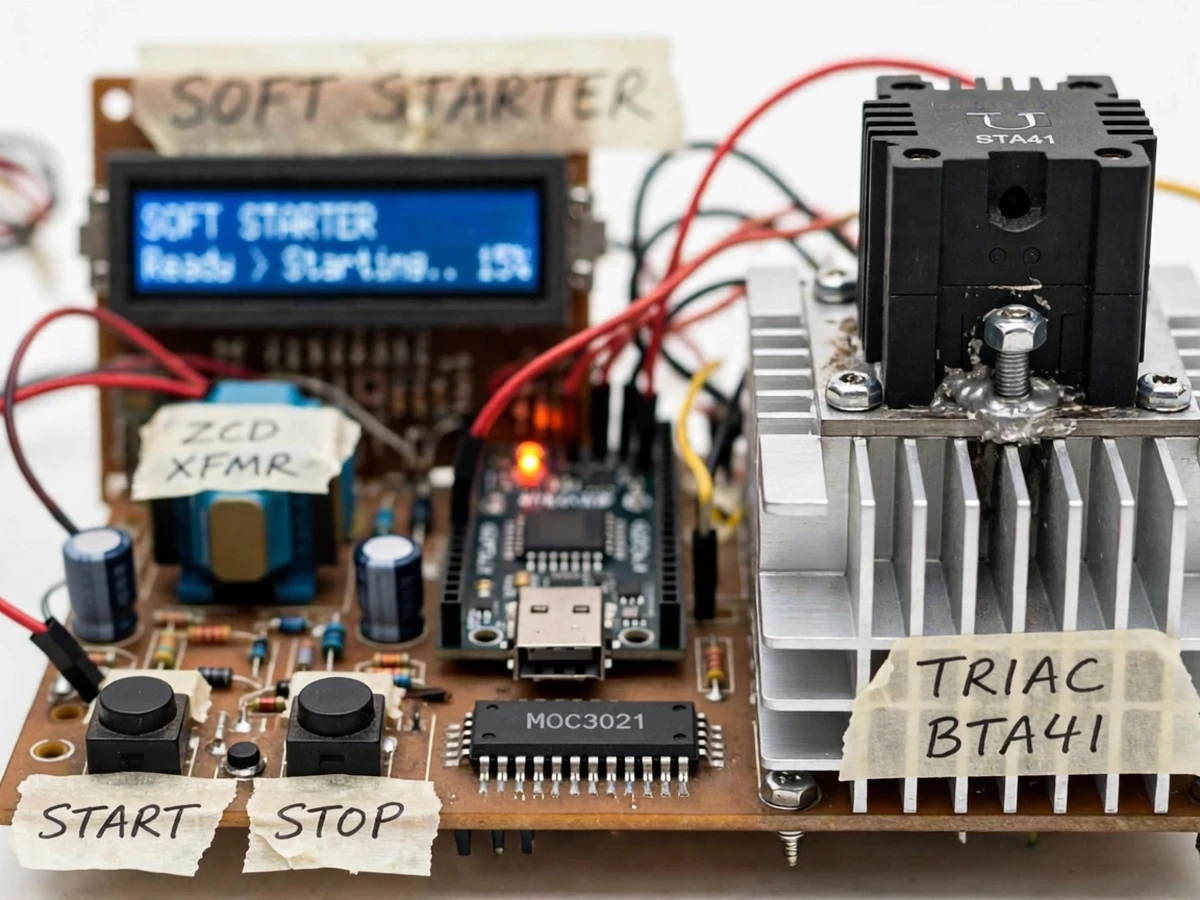
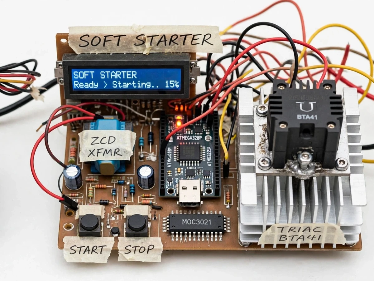
- [LCD ramp status display] A 16×2 LCD shows the controller state and live ramp percentage (for example "Starting.. 15%") during the ramp, plus a full-speed confirmation once the bypass relay engages.
- [Bypass relay at full speed] After the ramp completes, a relay shorts the triac so the motor runs on unswitched mains — removing triac conduction losses, switching heat and EMI during continuous running, exactly as commercial soft starters do.
- [RC snubber for inductive loads] A resistor–capacitor snubber across the triac suppresses voltage spikes from the motor's inductance and protects against spurious dv/dt turn-on, with values chosen per standard application-note practice.
- [START/STOP push-button control] Hardware START and STOP push buttons with labels drive the controller state machine: STOP during a ramp immediately drops the triac drive and resets to the ready state.
Optional customization (not in the base build): soft-stop ramp-down, overload current limit with trip, and remote start/stop can be developed on request. Future scope: a three-phase version and cloud-based start logging are possible extensions, not currently implemented.
What is included
- Working soft-starter prototype (control board, triac + heatsink, zero-cross detector, LCD, bypass relay, push buttons) wired to the 230 V, 40 W demo induction motor
- Complete Arduino firmware source with ramp timer and firing-angle logic
- Circuit and wiring documentation with mains-safety notes
- Component list with exact part numbers
- Safe testing procedure (isolation transformer, fuse check, wiring verification steps)
- Project abstract PDF
- Project report PDF (background, phase-angle control theory, methodology, observations)
- PPT presentation for final review
- Viva Q&A preparation document (triac operation, zero-cross detection, snubber design, ramp tuning)
Limitations & prerequisites
- This project switches 230 V AC mains: it must be assembled and tested under qualified supervision, ideally powered through an isolation transformer; the prototype carries no BIS/IEC safety certification and is an academic demonstrator, not an industrial product.
- Phase-angle starting reduces voltage but not frequency, so it suits light, fan-type loads best — high-inertia or heavily loaded starts may stall, which is a real characteristic of voltage-ramp soft starters, not a defect of this build.
- The demo motor is a 40 W single-phase induction unit; larger motors need the triac, heatsink, fuse and wiring re-rated per the BTA41 datasheet limits (40 A RMS maximum).
- The RC snubber is sized for the supplied motor; changing the load means re-checking snubber values against application-note guidance.
- Bypass relay timing is fixed in firmware after the ramp; an overload trip function is optional customization, not part of the base build.
Frequently Asked Questions
Is this project suitable for a final-year project?
Yes — for Electrical and Electronics programs. It demonstrates power electronics (triac switching), AC waveform control (phase angle), embedded timing (zero-cross interrupts), and mains-safety practice — a strong, honest hardware viva topic.
Which controller and power device are used?
An Arduino Nano (ATmega328P) runs the firing logic, and a BTA41-600B triac (40 A RMS, 600 V — datasheet values) switches the motor, triggered through an MOC3021 optocoupler that keeps the 5 V control side isolated from 230 V mains.
What motor can the soft starter drive?
The base build is demonstrated with a 230 V, 40 W single-phase induction motor. Heavier loads are possible up to the triac's datasheet limits, but the fuse, heatsink and snubber must be re-rated — the documentation explains how.
Is it safe to test a 230 V project?
The build includes a mains fuse, optoisolation and labeled wiring, and ships with a step-by-step safe testing procedure using an isolation transformer. It must be handled under qualified supervision and is not a certified industrial product.
Can the ramp time be changed?
Yes — the ramp duration is a firmware setting adjustable from 2 s to 30 s, so the student can demonstrate and compare different ramp profiles during the viva.
What will I receive with the project?
The working prototype with demo motor, Arduino firmware source, circuit/wiring documentation, component list, safe testing procedure, abstract PDF, report, PPT and a viva Q&A document. Suitable for B.E./B.Tech final-year projects in Electrical and Electronics engineering.
Components & software requirements
- Arduino Nano (ATmega328P)
- BTA41 power triac + MOC3021 optocoupler
- Optocoupler-based zero-crossing detector
- 16×2 character LCD
- Relay bypass module
- RC snubber network
- 230 V AC mains + isolation transformer (testing)
- Arduino IDE (firmware)
Delivery information
Built-to-order project. Delivery timeline is shared after order confirmation based on current queue.
Support terms
Complete documentation, setup guide, and viva preparation included. Support for setup and explanation provided.
Download free synopsis (PDF)
Enter your name and email — the synopsis PDF downloads immediately. We may send occasional project updates; no spam, unsubscribe anytime.