
More project photos (2)
The problem
Inverters convert DC (battery, solar) to AC, but the waveform quality decides what they can safely power. The simplest inverters output a square wave — fine for a resistive heater, but motors run hot and noisy on it, transformers saturate, and sensitive electronics misbehave. A sine-wave inverter synthesizes a smooth waveform by switching an H-bridge with sinusoidal pulse-width modulation (SPWM): the pulse widths follow a sine reference, and an LC filter averages the high-frequency switching into a clean 50 Hz sine. This modulation-plus-filter architecture is the foundation of UPS systems, solar inverters and motor drives. This project implements it on a bench scale: an Arduino generates complementary SPWM with dead-time, drives a MOSFET full bridge, and an LC filter plus step-up transformer delivers mains-frequency AC with overload and low-battery protection.
How it works
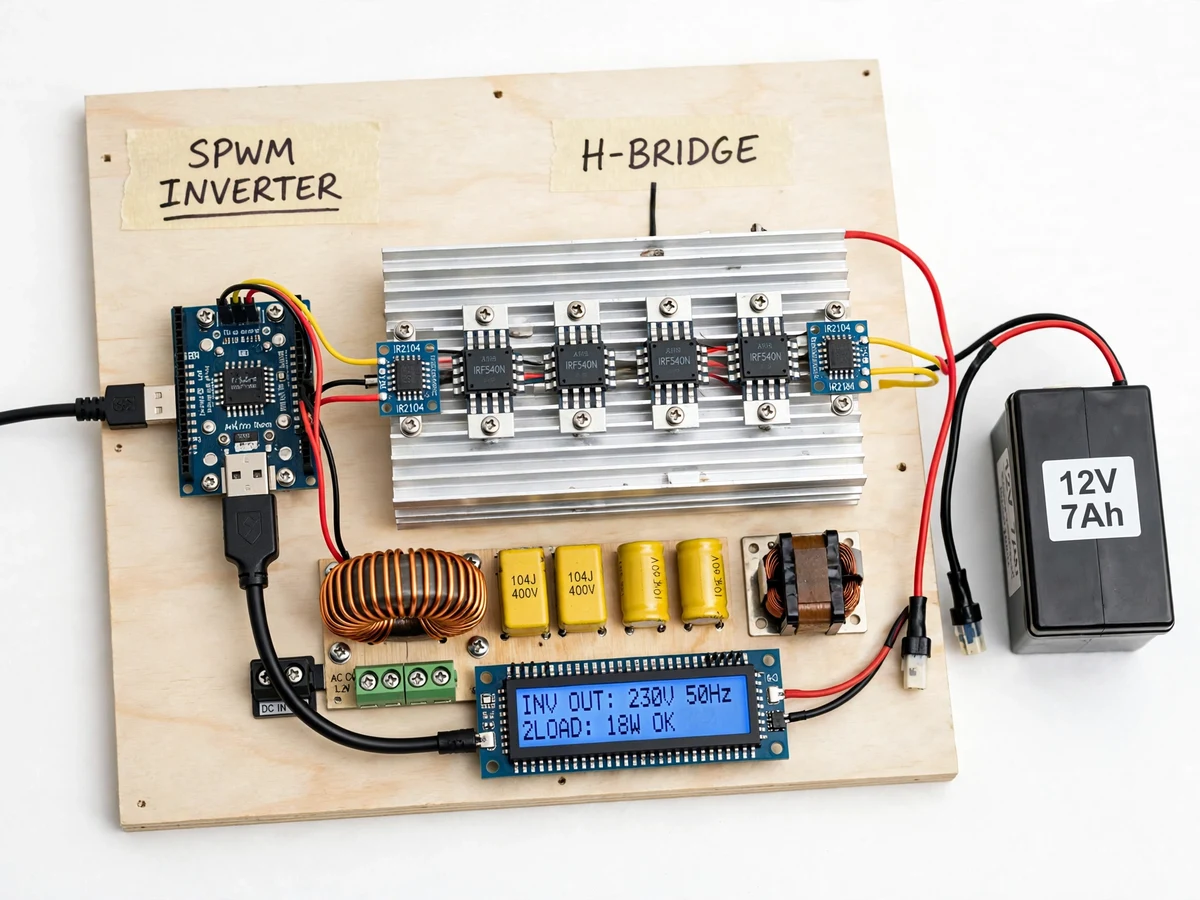
- The Arduino's firmware generates two complementary SPWM streams: a 50 Hz sine reference modulated onto a high-frequency carrier, with dead-time between the two halves.
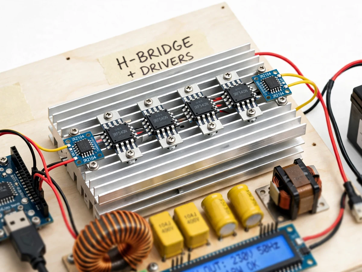
- Isolated gate drivers level-shift these signals to drive the high-side and low-side MOSFETs of the full H-bridge.
- The bridge chops the DC bus (12/24 V battery) into a high-frequency pulse train whose average follows the sine reference.
- The LC low-pass filter averages the pulse train, attenuating carrier harmonics and reconstructing a 50 Hz sine wave at low voltage.
- A step-up transformer raises the filtered output to usable AC mains level for the demo load.
- Output voltage and current are sensed continuously; on overload the firmware disables all gate drives, latches the fault and shows it on the LCD until reset.
- If the battery voltage falls below cut-off, the inverter shuts down cleanly and re-arms when the battery recovers.
Tech stack:
- Arduino Uno/Nano (ATmega328P)
- MOSFET full H-bridge with isolated gate drivers
- LC low-pass output filter (inductor + capacitor)
- Step-up transformer for mains-level output
- Output voltage and current sensing stage
- 16x2 character LCD
- Arduino IDE (C/C++ firmware)
- 12/24 V battery source and demo AC load
| Parameter | Value |
|---|---|
| Controller | Arduino Uno/Nano (ATmega328P) |
| Topology | Full-bridge (H-bridge) MOSFET inverter, SPWM modulated |
| Output | 50 Hz sine wave (design target); stepped up via transformer to mains-class AC for demo loads |
| Carrier frequency | High-frequency SPWM carrier set in firmware (tens of kHz class) |
| Filter | LC low-pass, corner frequency set between fundamental and carrier (design values in build notes) |
| Dead time | Programmed blanking interval between complementary switches |
| Protections | Overload/short-circuit latch-off with manual reset; battery low-voltage cut-off with hysteresis |
| Display | 16x2 LCD: DC input V, AC output V, frequency, fault status |
| Waveform quality | Design target: visibly clean sine on oscilloscope; THD is a design target, not a measured claim |
Project features
- [Sinusoidal PWM generation] The Arduino synthesizes SPWM by comparing a 50 Hz sine reference against a high-frequency carrier in firmware, with the modulation index adjustable for output voltage control.
- [Full-bridge MOSFET stage] Four MOSFETs in an H-bridge, driven through isolated gate drivers, switch the DC bus into the modulated waveform.
- [Dead-time insertion] A programmed blanking interval between high-side and low-side switching prevents shoot-through — a key inverter design detail, documented in the report.
- [LC output filter] A series inductor and shunt capacitor low-pass filter attenuates the switching-frequency harmonics, leaving the 50 Hz fundamental at the output.
- [Overload and short-circuit shutdown] Output current sensing trips the bridge on overload, with a latched fault that needs a manual reset — demonstrating inverter protection behavior.
- [Battery low-voltage cut-off] The inverter shuts down when the DC input sags below the set threshold, protecting the battery from deep discharge, and restarts with hysteresis.
- [Live output readout] An LCD shows DC input voltage, AC output voltage and frequency, and fault status.
What is included
- Working sine-wave inverter prototype (Arduino, H-bridge, gate drivers, LC filter, transformer, sensors, LCD)
- Complete firmware source code (SPWM generation, dead-time, protections, LCD)
- Circuit and wiring documentation with filter design notes
- Component list with voltage/current ratings
- Tuning procedure (buyer-run: set modulation index, verify waveform on oscilloscope, set protection thresholds)
- Project report PDF (inverter topologies, SPWM theory, filter design, methodology, test procedure)
- PPT presentation for final review
- Viva Q&A preparation document (SPWM, modulation index, dead-time, LC filter, shoot-through)
- Setup and demonstration guide
Limitations & prerequisites
- This is an academic demonstration prototype at modest power; it is not a UPS replacement and must not back-feed or parallel with mains supply under any circumstances.
- Output voltage regulation, waveform quality and efficiency are design targets verified by the buyer's own oscilloscope tests — nothing is pre-measured at build.
- The transformer and heatsinking size the practical demo load; sustained full-load running needs the thermal notes followed.
- Battery sizing and runtime are the buyer's selection; the report gives the calculation method rather than a claimed backup time.
- No galvanic output isolation beyond the transformer itself; standard bench high-voltage precautions apply during demo.
Frequently Asked Questions
What is SPWM and why use it?
Sinusoidal pulse-width modulation varies the H-bridge pulse widths along a sine reference; after LC filtering, the output averages to a smooth 50 Hz sine instead of a harsh square wave that overheats motors.
What is dead-time and why does it matter?
A short blanking interval between turning off one MOSFET and turning on its complement in the same leg. Without it both conduct simultaneously (shoot-through) and destroy the bridge.
What loads can it run in the demo?
Small mains-class demo loads sized to the transformer — lamps, a small fan — chosen during the buyer's setup within the thermal and current limits.
Can it be connected to house mains?
Absolutely not. It is a standalone demo inverter; paralleling with mains requires synchronization, certification and utility approval.
What are the main limitations?
Modest demo power; waveform and efficiency figures are design targets you verify yourself; no claimed backup time — the report shows how to calculate it.
Is this project suitable for a final-year project?
Yes — for Electrical programs. SPWM, dead-time, filter design and inverter protection are core power-electronics viva topics. Suitable for B.E./B.Tech final-year projects in Electrical engineering.
Components & software requirements
- Arduino Uno/Nano (ATmega328P)
- MOSFET full H-bridge with isolated gate drivers
- LC low-pass output filter (inductor + capacitor)
- Step-up transformer for mains-level output
- Output voltage and current sensing stage
- 16x2 character LCD
- Arduino IDE (C/C++ firmware)
- 12/24 V battery source and demo AC load
Delivery information
Built-to-order project. Delivery timeline is shared after order confirmation based on current queue.
Support terms
Complete documentation, setup guide, and viva preparation included. Support for setup and explanation provided.