
More project photos (1)
The problem
EV battery packs lose capacity and age faster when cells run hot, and imbalanced cells drag the whole pack down — in the worst case, thermal runaway is a fire risk. Most student and prototype EV builds have no thermal oversight at all: no per-cell temperature sensing, no cooling control, no automatic disconnect. This project adds an STM32-based battery management layer that continuously watches cell voltages and temperatures, estimates state of charge, balances cells during charging, and drives cooling fans — disconnecting the pack via a contactor if any cell crosses its safety temperature.
Four lithium-ion cells forming the prototype EV battery pack.
Follow the working sequence
How it works
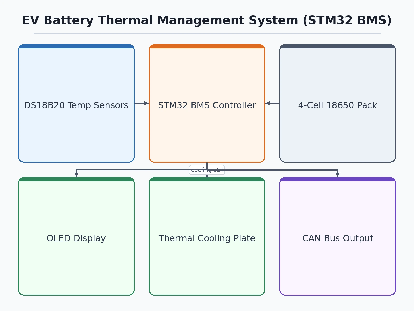
Four 18650 lithium-ion cells form a small battery-pack prototype. DS18B20 digital temperature sensors are positioned on individual cells to continuously measure their temperatures.
The STM32 controller collects temperature and battery-monitoring data, calculates or receives battery status information and displays important parameters such as individual cell temperature and estimated State of Charge on the OLED display.
When a predefined temperature threshold is exceeded, the controller can activate the prototype cooling system, such as a cooling fan, coolant pump or thermal plate arrangement. CAN bus communication allows battery information and diagnostic values to be exchanged with another controller or demonstration unit.
State-of-charge estimation method: the firmware estimates SoC by coulomb counting — integrating pack current measured by the Hall-effect sensor over time — corrected with an open-circuit-voltage lookup whenever the pack is at rest. The estimate re-anchors to 100% on every full charge and to 0% at the low-voltage cutoff; between these calibration points the reading drifts, so it should be treated as an estimate (design target ±5% after the calibration procedure documented in the report), not a laboratory measurement.
Project features
- Real-time temperature monitoring of individual battery cells
- Multi-point DS18B20 temperature sensing across the battery pack
- STM32-based battery monitoring and thermal control
- State of Charge (SoC) estimation and battery-status display
- OLED display showing individual cell temperatures and battery condition
- Thermal cooling plate for battery-temperature management demonstration
- CAN bus communication for battery-system data exchange
- Detection of abnormal or excessive battery temperature
What is included
- Source code
- Circuit diagram
- Component list / BOM
- Project report
- Abstract
- PPT / presentation
- Installation guide
- Setup support
- Demonstration video
- System architecture and thermal-control explanation
Advantages
- Real-time per-cell temperature monitoring with multi-point DS18B20 sensing across the battery pack.
- State of Charge (SoC) estimation with individual cell temperatures and battery condition on an OLED display.
- STM32-based BMS demonstrating thermal monitoring and cooling-plate control concepts used in electric vehicles.
- CAN bus communication demonstrating battery-system data exchange.
- Detection of abnormal or excessive cell temperature.
Disadvantages
- Academic prototype — not an automotive-certified BMS or thermal-management system.
- Uses a small 4-cell battery pack; it does not represent the voltage, current or thermal load of a full-scale EV pack.
- Temperature accuracy depends on sensor placement, calibration and thermal contact with individual cells.
- State of Charge estimation is for demonstration and may be less accurate than commercial automotive battery-management algorithms.
- The cooling system demonstrates thermal-control principles but is not designed for high-power EV battery packs; CAN is prototype-level and would need more protocol/hardware work for vehicle integration.
Limitations & prerequisites
- This is an academic EV battery-management prototype and not an automotive-certified BMS or thermal-management system.
- The prototype uses a small 4-cell battery pack and does not represent the voltage, current or thermal load of a full-scale EV battery pack.
- Temperature accuracy depends on sensor placement, calibration and thermal contact with individual cells.
- State of Charge estimation is intended for demonstration and may be less accurate than commercial automotive battery-management algorithms.
- The cooling system demonstrates thermal-control principles but is not designed for high-power EV battery packs.
- CAN communication is demonstrated at prototype level and may require additional hardware or protocol development for integration with an actual vehicle network.
- Lithium-ion battery testing requires suitable protection circuitry and safe operating practices.
- Hardware components and specific BMS modules may vary depending on availability.
- Additional features such as active cell balancing, cloud monitoring, mobile applications or advanced battery analytics require separate customisation.
- Delivery time may change if additional battery hardware, cooling mechanisms or communication features are requested.
Components & software requirements
Hardware requirements:
STM32 development board/controller, 4 × 18650 lithium-ion cells, suitable battery holder, BMS/protection circuit, DS18B20 temperature sensors, OLED display, CAN transceiver module, thermal cooling plate, cooling fan or miniature pump if required, regulated power circuitry, wiring and prototype mounting base.
Software requirements:
Embedded C firmware, STM32 HAL libraries, sensor-reading logic, thermal-control algorithm, battery-monitoring logic and CAN communication firmware.
Delivery information
Built to order. Typical build time 3–4 weeks after order confirmation and pack-configuration freeze (cell count, series/parallel layout, chemistry, cooling arrangement). The unit is bench-tested on a representative cell group — protection trip, fan staging, and SoC calibration — before dispatch.
Support terms
- 30 days of build support over WhatsApp/email: wiring doubts, firmware questions, and the SoC calibration walkthrough.
- One video call to bring the BMS up on your pack and verify protection and balancing behavior.
- The report and PPT document the thermal design, the SoC estimation method, and the safety limits for your viva.
Download free synopsis (PDF)
Enter your name and WhatsApp number — the synopsis PDF downloads immediately. We may send occasional project updates on WhatsApp; no spam.