
More project photos (2)
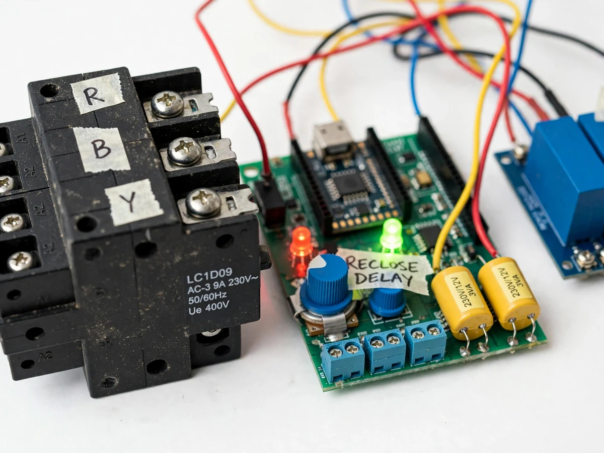
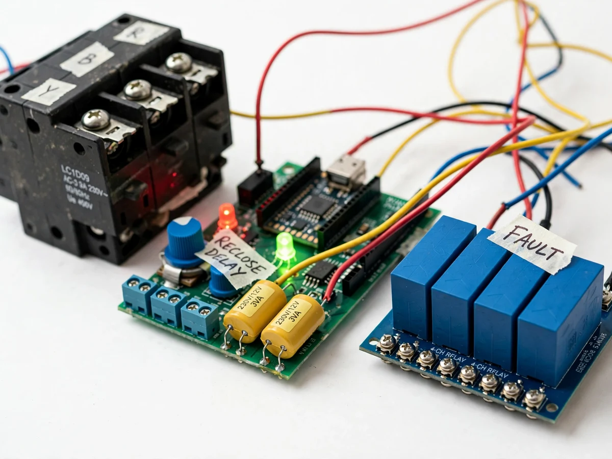
The problem
On rural agricultural feeders, phase faults are daily life: a blown fuse, a snapped line or a loose joint can kill one phase while the other two keep going. A 3-phase pump motor running on two phases - single-phasing - draws heavy overcurrent in the healthy windings and can burn out in minutes while the farmer is away. Standard MCBs and fuses do not protect against this; they see only slightly elevated current and stay closed. The classical answer is a single-phase preventer: sense all three phases continuously and disconnect the motor the moment one fails or voltage drifts out of safe bounds. The next problem is the restart: after a transient fault, the farmer must walk to the panel, and hasty restarts on an unstable supply harm the motor. Auto-reclosure with a safe delay solves both - the contactor re-closes only after the supply has stayed healthy through the countdown. This project builds that protection chain as a working prototype: isolated phase sensing, threshold comparison, contactor trip and timed auto-reclosure, with a calibration procedure the student performs and documents.
R, Y, B phases plus neutral feeding the pump panel.
Follow the working sequence
How it works
- Each supply phase (R, Y, B to neutral) feeds a small 230/12 V sensing transformer, producing an isolated low-voltage AC replica of that phase.
- The three secondaries are rectified, filtered and divided to DC levels proportional to each phase voltage, feeding three ADC channels of an Arduino Nano.
- Firmware compares each reading against the potentiometer-set undervoltage and overvoltage thresholds; a reading below the design loss level on any channel is treated as a lost phase.
- On any fault, the controller de-energizes the relay driver, the contactor coil drops and the pump motor is disconnected; the FAULT LED lights and the phase LEDs show which phase failed.
- The controller watches the supply continuously; when all three phases stay within tolerance, the reclosure countdown starts (design range 30–300 s, set by the delay potentiometer) with the RECLOSING LED lit.
- If a fault reappears during the countdown, the timer aborts and restarts only after the supply is healthy again - no reclosure onto a sick supply.
- When the countdown completes, the relay driver re-energizes the contactor and the pump restarts automatically; in manual mode the system instead waits for the reset button.
- The test push-button forces a simulated phase loss, so the examiner can watch the full trip-and-reclose cycle in under a minute at a short delay setting.
Tech stack:
- Arduino Nano (ATmega328P, 10-bit ADC)
- Three 230/12 V isolation sensing transformers
- Bridge rectifier + RC filter + divider conditioning stage
- 4-channel electromechanical relay module with driver stage
- 3-pole AC-3 power contactor as trip actuator
- Potentiometers for threshold and delay adjustment
- Panel LEDs (phase, fault, reclosing) + selector switch
- Arduino IDE (C/C++ firmware)
| Parameter | Value |
|---|---|
| Supply sensed | 415 V AC, 3-phase, 50 Hz (design) |
| Sensing | Three 230/12 V isolation transformers, phase-to-neutral |
| Phase-loss detection | Any phase below ~50% of nominal (design threshold, buyer-calibrated) |
| Undervoltage cutoff | Adjustable design range ~300–380 V line, potentiometer-set |
| Overvoltage cutoff | Adjustable design range ~430–480 V line, potentiometer-set |
| Reclosure delay | Adjustable design range 30–300 s, potentiometer-set |
| Output | 3-pole contactor, AC-3 duty, 400 V class (rating selected to the pump in the build) |
| Controller | Arduino Nano (ATmega328P), firmware in C/C++ |
| Indication | 3 phase LEDs + red FAULT LED + green RECLOSING LED |
| Modes | Auto-reclosure / manual-reset, panel selector switch |
| Power | Control supply derived from sensing transformers + 12 V / 5 V regulation (design) |
Project features
- [Three-phase voltage sensing] Three 230/12 V isolation transformers sense each phase-to-neutral voltage independently, giving safe, galvanically isolated replicas of the supply phases.
- [Phase-loss detection] The controller trips the contactor when any single phase collapses below the design loss threshold, disconnecting the pump before single-phasing can overheat the motor windings.
- [Undervoltage/overvoltage cutoffs] Separate adjustable thresholds for low and high voltage; sustained undervoltage or overvoltage on any phase trips the output just like a lost phase.
- [Adjustable auto-reclosure delay] After the supply returns to tolerance, a countdown (design range 30–300 s, potentiometer-set) runs before reclosure, letting the motor cool and the supply stabilize.
- [Contactor trip output] A relay driver stage drops a 3-pole AC-3 contactor coil to disconnect the pump - the same trip-chain architecture used in real motor-control panels.
- [LED fault indication] Per-phase LEDs show which phase failed, plus a red FAULT LED and a green RECLOSING LED during the countdown, giving the examiner a readable demo.
- [Manual/auto selector] A panel switch chooses automatic reclosure or manual-reset lockout, so the student can demonstrate both protection philosophies.
- [Test push-button] Simulates a phase loss on demand, letting the trip and reclosure sequence be demonstrated repeatedly without touching the real supply.
What is included
- Working single-phase preventer prototype (sensing stage, control board, relay module, contactor, LED panel)
- Complete firmware source code (sensing, thresholds, trip logic, reclosure timer, mode select)
- Circuit and wiring documentation with transformer and divider sizing notes
- Component list with ratings and contactor selection guidance
- Threshold and delay calibration procedure (buyer-run: set and verify trip levels)
- Project report PDF (protection background, single-phasing theory, methodology, test procedure)
- PPT presentation for final review
- Viva Q&A preparation document (single-phasing, protection coordination, contactor duty classes)
- Setup and demonstration guide
Limitations & prerequisites
- An academic demonstration prototype, not utility-grade protection equipment; it must not be installed on a real farm supply without a licensed electrician's panel work.
- Trip thresholds and the reclosure delay are design settings verified by the buyer's own calibration procedure - the prototype ships uncalibrated and final values depend on the transformers and potentiometers used.
- This protects the motor against SUPPLY faults (phase loss, under/overvoltage); it does not provide motor overload or short-circuit protection - a thermal overload relay belongs in series in any real installation.
- The contactor rating must be selected for the pump motor it will switch; the prototype ships with a demonstration-class contactor and the selection procedure is in the docs.
- Auto-reclosure does not diagnose why the fault happened; on a persistent fault the timer simply keeps waiting, which protects the motor but needs the farmer to investigate.
- Correct phase-to-neutral wiring and proper earthing are required; mis-wired sensing gives misleading protection.
- The sensing stage assumes 50 Hz supply; other frequencies are outside the design.
Frequently Asked Questions
Why do pump motors burn out on single-phasing?
A 3-phase induction motor forced to run on two phases draws heavy overcurrent in the healthy windings to deliver its shaft power, overheating them; insulation fails and the motor burns. Ordinary fuses and MCBs see only mildly elevated current and do not trip - which is exactly why a dedicated preventer exists.
What does auto-reclosure add over a plain preventer?
A plain preventer disconnects the pump and waits for someone to reset it - a long walk to the panel for a transient fault. Auto-reclosure reconnects automatically, but only after the supply has stayed healthy through a safe countdown, so the motor is not switched onto a flickering supply.
How is the reclosure delay set?
A panel potentiometer sets it across the design range of 30–300 seconds; the calibration procedure shows how to verify the delay and the trip thresholds on your own build before the demo.
Can this be installed on a real farm pump?
Not as shipped. It is an academic prototype demonstrating protection principles. A real installation needs panel-grade construction, correct contactor and overload sizing, and installation by a licensed electrician.
Which controller is used?
An Arduino Nano (ATmega328P). It samples the three conditioned phase voltages on its 10-bit ADC, applies the threshold logic and reclosure timer, and drives the contactor through the relay stage.
Is this project suitable for a final-year project?
Yes - for Electrical engineering programs. It demonstrates voltage sensing, protection thresholds, contactor trip chains and timer logic, with a calibration procedure and protection theory that make strong viva material. Suitable for B.E./B.Tech final-year projects in Electrical engineering.
Components & software requirements
- Arduino Nano (ATmega328P, 10-bit ADC)
- Three 230/12 V isolation sensing transformers
- Bridge rectifier + RC filter + divider conditioning stage
- 4-channel electromechanical relay module with driver stage
- 3-pole AC-3 power contactor as trip actuator
- Potentiometers for threshold and delay adjustment
- Panel LEDs (phase, fault, reclosing) + selector switch
- Arduino IDE (C/C++ firmware)
Delivery information
Built-to-order project. Delivery timeline is shared after order confirmation based on current queue.
Support terms
Complete documentation, setup guide, and viva preparation included. Support for setup and explanation provided.
Download free synopsis (PDF)
Enter your name and email — the synopsis PDF downloads immediately. We may send occasional project updates; no spam, unsubscribe anytime.