
More project photos (4)
The problem
Earth faults — current leaking from a phase conductor to earth through insulation failure, moisture or damaged cable — are a leading cause of electric shock, equipment burnout and electrical fires. Ordinary overcurrent protection (MCBs, fuses) cannot see small leakage currents: a 30 mA fault to earth will not trip a 16 A breaker, yet it can be lethal. This is the gap residual-current protection fills. A core-balance current transformer passes all phase conductors through one magnetic core; under healthy conditions the vector sum is zero, and any imbalance is the earth-fault current itself. Utility and industrial panels implement this with dedicated protection relays, but the principle is rarely demonstrated hands-on in college labs. This project closes that gap: a working prototype that senses residual current with a CBCT, processes it on an Arduino, and trips a relay/contactor when leakage crosses a set pickup — with the trip logic, burden sizing and calibration procedure all documented for the student's report and viva.
How it works
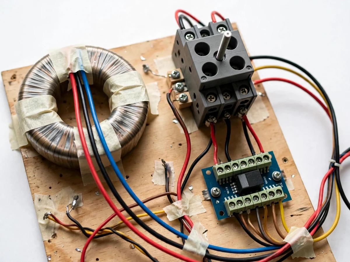
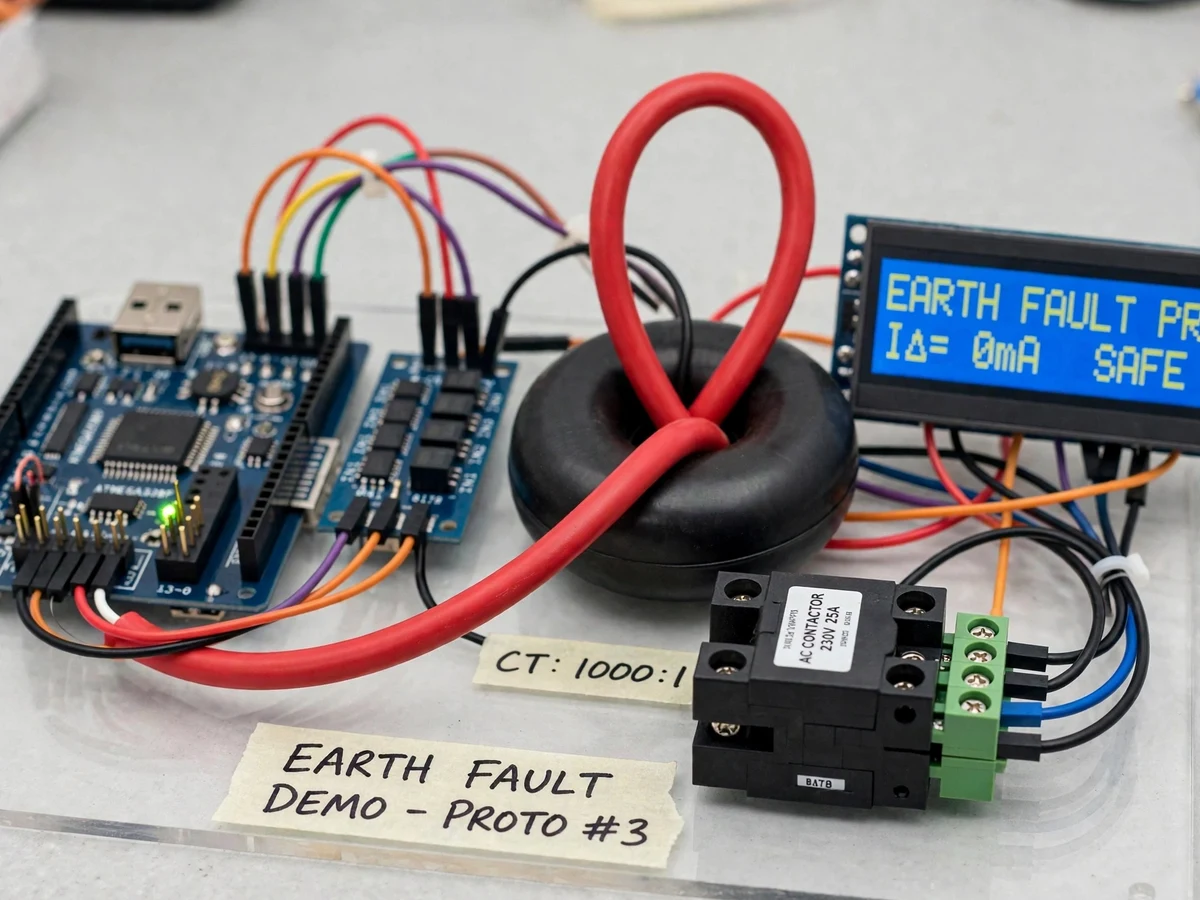
- The phase and neutral conductors of the test load pass through the core-balance CT, which outputs the residual (vector-sum) current.
- The CT secondary feeds a burden resistor sized for the CT ratio; the resulting AC voltage is rectified, filtered and scaled to the Arduino's 0–5 V ADC range.
- The firmware samples the conditioned signal, computes the residual current and compares it against the configured pickup threshold.
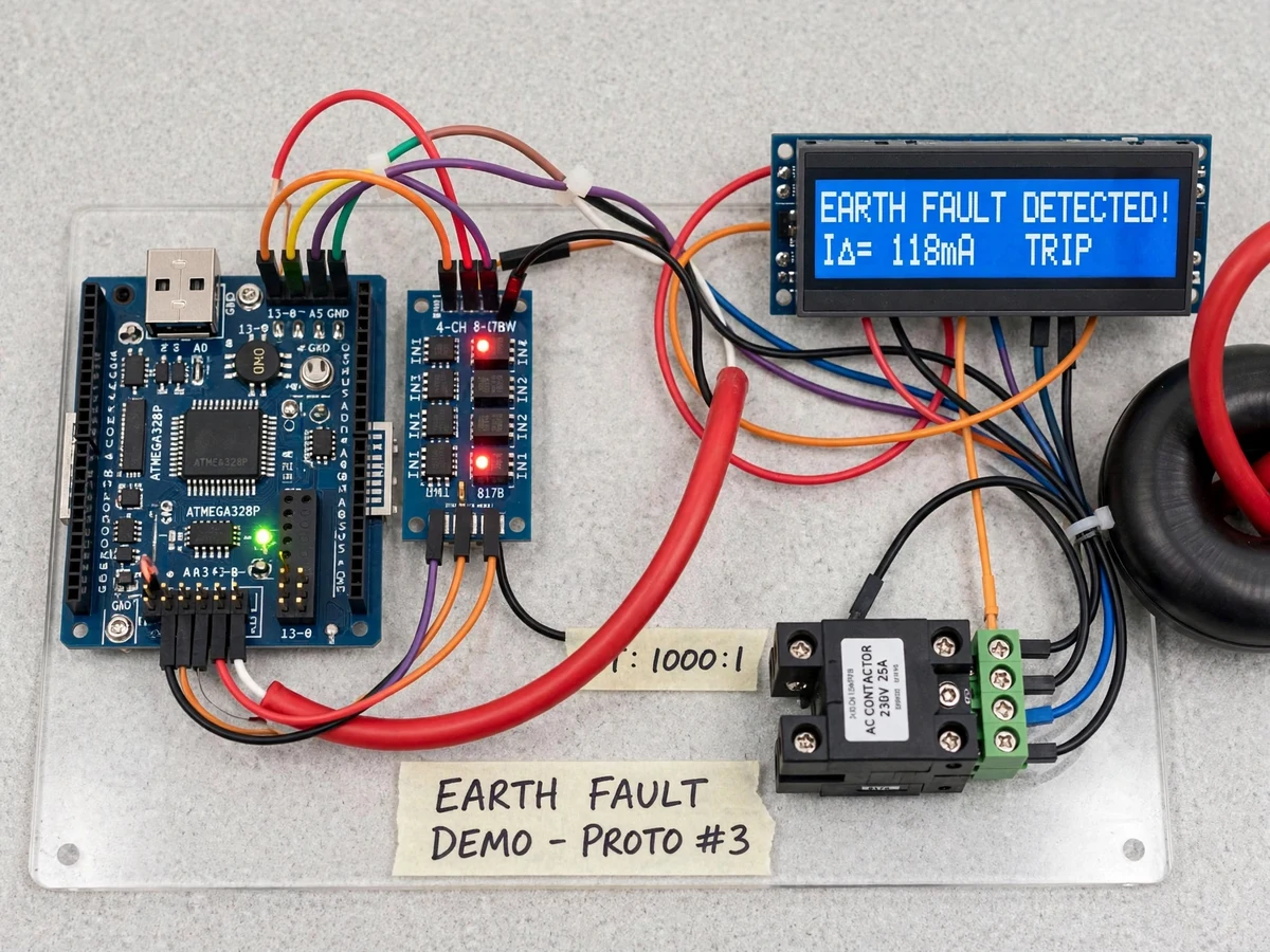
- When the residual current exceeds pickup for the programmed confirmation time, the Arduino energizes the trip relay.
- The relay drops the contactor coil, disconnecting the load; the LCD switches to FAULT TRIPPED and a buzzer sounds.
- The contactor remains open until the manual reset button is pressed, after which the system re-arms and the LCD returns to NORMAL.
Tech stack:
- Arduino Uno (ATmega328P)
- Toroidal core-balance current transformer
- Burden resistor + bridge rectifier + filter conditioning stage
- 4-channel electromechanical relay module
- Single-phase contactor as trip actuator
- 16x2 character LCD
- Arduino IDE (C/C++ firmware)
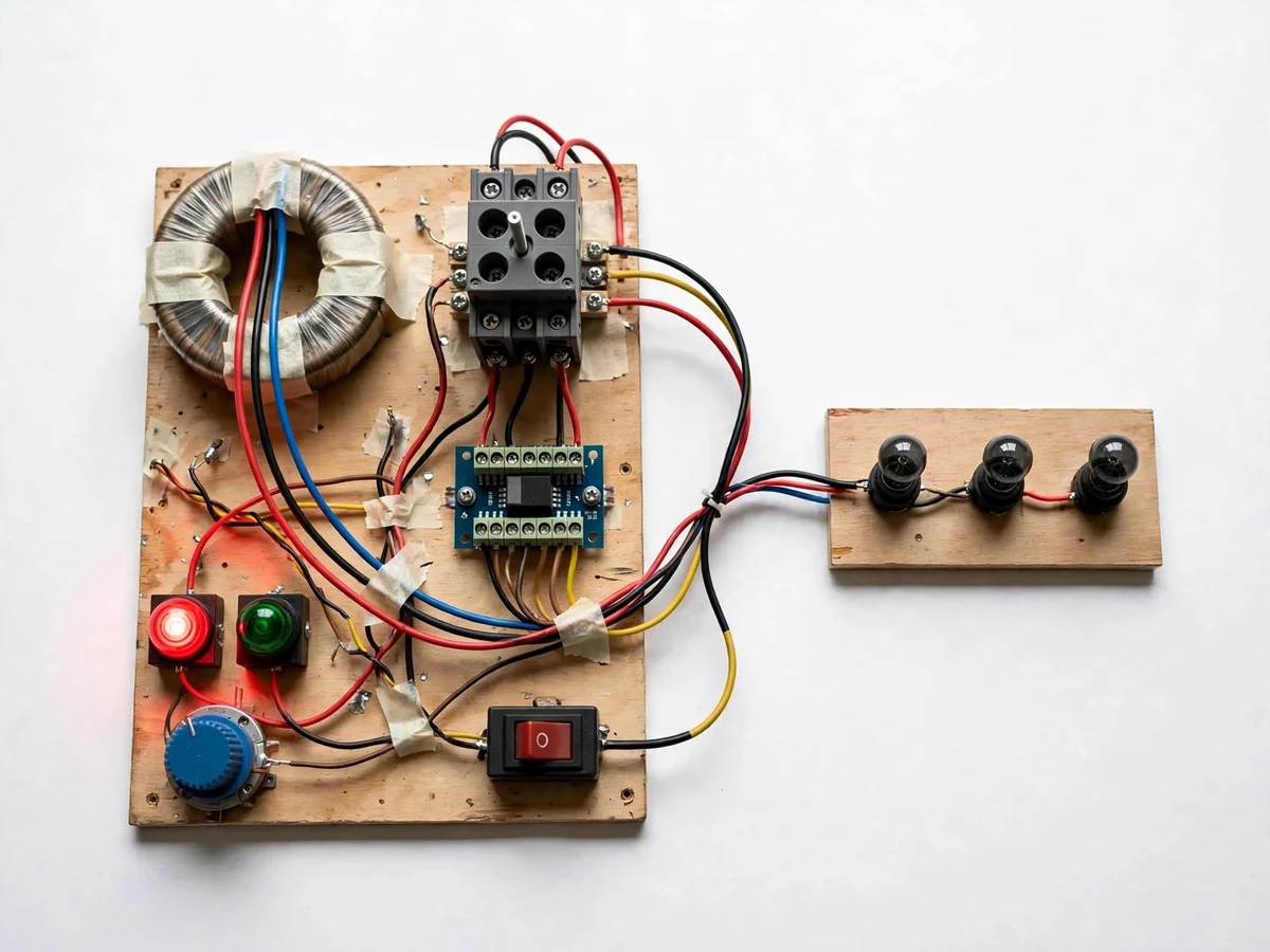
- Single-phase test load rig with simulated fault injection
| Parameter | Value |
|---|---|
| Controller | Arduino Uno (ATmega328P), 10-bit ADC |
| Sensing element | Toroidal core-balance CT (all conductors through one core) |
| Measured quantity | Residual (vector-sum) current = earth-leakage current |
| Pickup setting | Adjustable via potentiometer constant; design range 10–100 mA residual, set during buyer calibration |
| Trip output | Relay-driven contactor coil dropout; manual reset (lockout) |
| Display | 16x2 LCD: live residual current + NORMAL / FAULT TRIPPED state |
| Conditioning | Burden resistor sized for CT ratio, bridge rectifier, RC filter, divider to 0–5 V |
| Power | 230 V AC test load circuit; 5 V DC logic supply |
| Demo fault | Push-button simulated imbalance for on-demand trip demonstration |
Project features
- [Core-balance CT sensing] All conductors pass through a single toroidal CBCT; the vector sum of phase currents is zero in healthy conditions, and the residual output directly represents earth-leakage current.
- [Configurable pickup threshold] The trip pickup is adjustable via a potentiometer/software constant, so the student can demonstrate sensitive versus coarse protection settings during the demo.
- [Relay/contactor trip output] On pickup, the Arduino drives a relay that drops a contactor coil, visibly disconnecting the test load — the same trip-chain architecture used in real panels.
- [LCD fault status display] A 16x2 LCD shows live residual current and the NORMAL / FAULT TRIPPED state, giving the examiner a readable demo.
- [Burden and rectifier conditioning] The CT secondary is loaded with a sized burden resistor, rectified and filtered to a DC level the Arduino ADC can sample — the conditioning stage is fully documented.
- [Manual reset logic] After a trip, the contactor stays open until the operator presses reset, demonstrating lockout behavior; auto-reclose is intentionally not implemented.
- [Test push-button] A test button injects a simulated imbalance so the trip can be demonstrated on demand without creating a real fault.
What is included
- Working earth-fault protection prototype (Arduino, CBCT, relay, contactor, LCD, test load rig)
- Complete firmware source code (sensing, pickup logic, trip/reset, LCD)
- Circuit and wiring documentation with burden-resistor sizing notes
- Component list with ratings
- Pickup calibration procedure (buyer-run: set and verify trip levels)
- Project report PDF (protection background, CBCT theory, methodology, test procedure)
- PPT presentation for final review
- Viva Q&A preparation document (residual current, CT theory, relay coordination basics)
- Setup and demonstration guide
Limitations & prerequisites
- This is an academic demonstration prototype, not a certified protection relay; it must not be installed on real building wiring.
- Trip pickup and timing are design settings verified by the buyer's own calibration procedure — the prototype ships uncalibrated and final values depend on the CT and burden used.
- Single-phase test rig only; a three-phase CBCT pass-through is a possible extension, not part of the base build.
- CT accuracy and linearity depend on the burden resistor value and the CT core quality; saturation at high fault currents is not characterized.
- The Arduino ADC resolution limits how finely small leakage steps can be resolved; this is a teaching limitation, not a measurement instrument.
Frequently Asked Questions
Which controller is used?
An Arduino Uno (ATmega328P). It samples the conditioned CT signal on its 10-bit ADC, runs the pickup comparison and drives the trip relay and LCD.
How is the pickup threshold set?
Via a potentiometer/software constant, and the calibration procedure shows how to verify the actual trip level with a test current. Final pickup values come from your build, not from a pre-claimed number.
Can this protect a real house or lab?
No. It is an academic prototype for demonstrating residual-current protection principles. Real installations need certified RCCBs/ELCBs installed by a licensed electrician.
What power supply is needed?
A 230 V AC supply for the test load circuit (handled through the contactor) and a 5 V DC supply for the Arduino logic.
What are the main limitations?
Uncalibrated at build — you calibrate pickup yourself; single-phase demo rig; CT accuracy depends on burden sizing; not a certified protection device.
Is this project suitable for a final-year project?
Yes — for Electrical and Electronics programs. It demonstrates CT theory, residual-current sensing, relay trip logic and calibration discipline, all strong viva material. Suitable for B.E./B.Tech final-year projects in Electrical and Electronics engineering.
Components & software requirements
- Arduino Uno (ATmega328P)
- Toroidal core-balance current transformer
- Burden resistor + bridge rectifier + filter conditioning stage
- 4-channel electromechanical relay module
- Single-phase contactor as trip actuator
- 16x2 character LCD
- Arduino IDE (C/C++ firmware)
- Single-phase test load rig with simulated fault injection
Delivery information
Built-to-order project. Delivery timeline is shared after order confirmation based on current queue.
Support terms
Complete documentation, setup guide, and viva preparation included. Support for setup and explanation provided.