
More project photos (2)
The problem
Motor winding temperature is one of the earliest signs that an industrial motor is in trouble, yet on many small machines it is never measured. Overloading, blocked ventilation, a failing bearing, or a long run under a heavy load all push winding temperature upward, and the heat attacks the winding insulation before the motor stops turning. Once insulation degrades, a shorted turn or a burnt winding can follow, taking the motor out of service. The Motor Winding Temperature Monitor with PT100 and Relay Trip for Industrial Motors addresses this gap by watching winding temperature continuously with a PT100 resistance sensor mounted on the motor body and tripping a relay when a user-set limit is crossed. A buzzer and display warn the operator at the same time. The build is a bench demonstrator on a small motor model, not a certified industrial protection device, and its thresholds are design targets set by the user for demonstration.
Builder note from the build: the prototype uses 3-wire PT100 wiring so the MAX31865 converter can cancel lead resistance. With 2-wire wiring, the same leads would add their own resistance to the reading and shift every temperature upward, which is why the build keeps the lead pair matched in length and routed together. The mechanism behind the reading is first-principles simple: platinum resistance rises with temperature, by approximately 0.385 Ω per °C near 0 °C for a PT100, so temperature is recovered from resistance rather than from a voltage that drifts with supply noise.
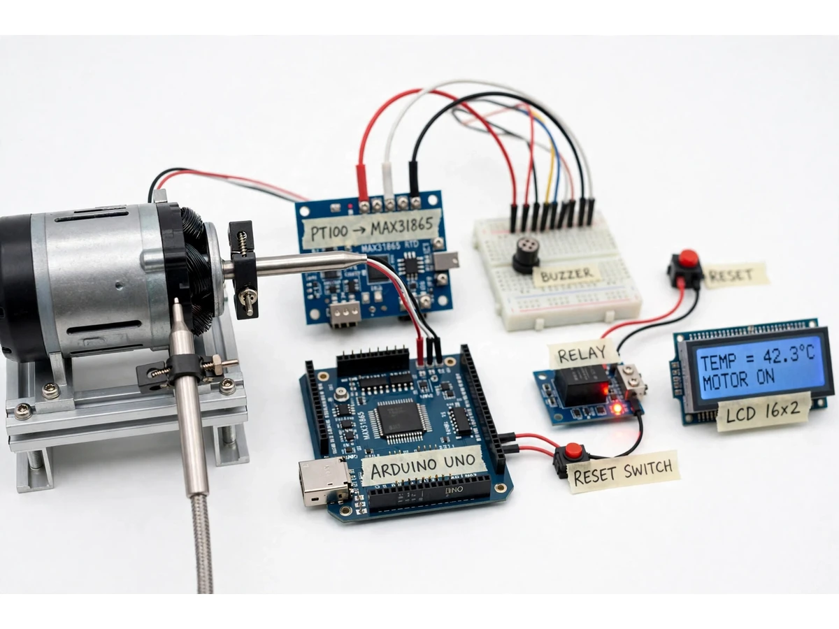
A PT100 probe clamped to the bench motor housing changes resistance as winding temperature rises.
Follow the working sequence
How it works
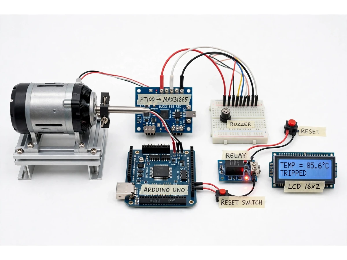
The Motor Winding Temperature Monitor with PT100 and Relay Trip for Industrial Motors works as a continuous sense, compare, and act loop. The PT100 probe, clamped to the bench motor housing, changes resistance as the winding temperature rises, and the MAX31865 converter turns that resistance into a digital temperature value that the Arduino reads over SPI. The controller compares each new reading against two user-set limits: a lower warning level that sounds the buzzer and a higher trip level that drives the relay. Below both limits the motor runs normally and the display shows the live temperature. At the warning level the buzzer sounds while the motor keeps running, giving the operator a chance to act. At the trip level the relay opens, the motor stops, the display shows the tripped state, and the trip latches until the reset button is pressed after the motor has cooled.
- The PT100 probe, clamped against the bench motor housing, changes resistance as winding temperature rises, following the platinum resistance-temperature relationship.
- The MAX31865 converter measures that resistance through the 3-wire connection, cancels lead resistance, and converts it to a digital temperature value.
- The Arduino reads the temperature over SPI, applies the converter's linearisation, and updates the LCD with the live temperature in °C and the current motor state.
- Each reading is compared with the user-set warning limit; crossing it sounds the buzzer while the motor keeps running.
- Each reading is also compared with the higher user-set trip limit; crossing it drives the single-channel relay module to open the motor supply circuit.
- The trip latches in firmware: the relay stays open and the display shows the tripped state even as the motor cools down.
- After the motor has cooled, pressing the reset button clears the latch, silences the buzzer, and allows the motor to be restarted for the next demonstration run.
Tech stack:
- Arduino Uno (ATmega328P controller)
- PT100 RTD sensor · 3-wire probe
- MAX31865 RTD-to-digital converter
- Single-channel relay module
- 16 × 2 character LCD display
- Buzzer · reset push-button
- Arduino IDE (C++ firmware)
- Bench motor model · low-voltage supply
| Parameter | Value |
|---|---|
| Sensor | PT100 RTD · resistance 100 Ω at 0 °C (datasheet value) |
| Temperature coefficient | 0.00385 Ω/Ω/°C (datasheet value, IEC 60751) |
| Resistance change | Approximately 0.385 Ω per °C near 0 °C (datasheet value) |
| Converter | MAX31865 RTD-to-digital · 15-bit ADC (datasheet value) |
| Nominal resolution | 0.03125 °C (datasheet value, varies with RTD non-linearity) |
| Conversion time | 21 ms maximum (datasheet value) |
| Reference resistor | 400 Ω (design target, for PT100) |
| Controller | Arduino Uno · ATmega328P |
| Display | 16 × 2 character LCD |
| Relay | Single-channel module · contact rating 10 A at 250 V AC (design target) |
| Warning limit | User-set design target · default 70 °C |
| Trip limit | User-set design target · default 85 °C |
| Power supply | 5 V DC (design target) for logic · bench motor on a separate low-voltage supply |
| Operating mode | Bench demonstrator only · not a certified industrial protection device |
Project features
The Motor Winding Temperature Monitor with PT100 and Relay Trip for Industrial Motors combines four capabilities that matter most for motor protection work: accurate RTD temperature sensing, a live local display, a two-stage warning and trip response, and a latching trip that stays off until a person resets it. The PT100 sensor and MAX31865 converter give a stable digital temperature reading instead of a rough analogue estimate, so threshold decisions rest on a repeatable measurement. The LCD shows the live temperature and the motor state at a glance, while the buzzer draws attention the moment a warning level is reached. When the trip level is crossed, the relay opens the motor supply circuit and latches, so a cooling motor cannot restart itself unattended. Together these capabilities turn a simple temperature reading into a complete protection demonstration that students can explain, test, and present.
- [PT100 RTD temperature sensing] A stainless steel PT100 probe clamped to the bench motor housing tracks winding temperature through the resistance of platinum, a measurement principle trusted in industrial instrumentation for its stability and repeatability.
- [MAX31865 digital conversion] The MAX31865 RTD-to-digital converter reads the PT100 over a 3-wire connection and delivers a digital temperature value to the controller, with lead-resistance cancellation and built-in open and short fault detection.
- [Live LCD temperature display] A 16 × 2 character LCD shows the live winding temperature in °C together with the motor state, so the reading and the protection state are visible without a computer or phone.
- [Two-stage warning and trip] A lower warning level sounds the buzzer while the motor keeps running, and a higher trip level opens the relay, giving the operator a chance to act before the motor is stopped.
- [Latching relay trip with manual reset] Once tripped, the relay stays open even as the motor cools, and the motor restarts only after the reset button is pressed, preventing an unattended automatic restart.
- [User-set thresholds] Warning and trip limits are set in the firmware as clearly labelled constants, so the demonstration can be tuned to different motor models and classroom test conditions.
- [Sensor fault indication] If the PT100 lead breaks or shorts, the converter flags the fault and the display reports a sensor fault instead of a plausible-looking false temperature.
What is included
- Working bench prototype: bench motor model, PT100 probe, MAX31865 board, Arduino Uno, relay module, LCD, buzzer and reset button
- Complete firmware source code with labelled warning and trip constants
- Circuit diagram and wiring documentation, including the 3-wire PT100 connection
- Component list with part values used in the build
- Setup and demonstration instructions, including how to trigger a warning and a trip safely
- Project report PDF (background, RTD theory, methodology, results discussion)
- PPT presentation for final review
- Viva Q&A preparation document (RTD principle, 3-wire wiring, trip logic, limitations)
Limitations & prerequisites
- This is a bench demonstrator on a small motor model, not a certified industrial protection device, and it must not be wired into a real industrial motor installation.
- The probe measures housing temperature near the winding, not the internal winding hot-spot temperature, so readings lag and under-read the hottest point inside the motor.
- Trip and warning limits are user-set design targets, not protection settings validated for any specific real motor or insulation class.
- PT100 accuracy depends on sensor tolerance class and lead wiring; the build assumes a correctly wired 3-wire connection and a 400 Ω reference resistor (design target).
- The relay module switches the low-voltage bench motor supply only; switching mains-powered equipment would need a separately rated contactor and qualified supervision.
- Response time is limited by the thermal mass of the probe and housing, so a sudden internal fault heats the sensor only after a delay of seconds to minutes (expected behaviour).
Frequently Asked Questions
Is this project suitable for a final-year project?
Yes, it fits Electrical Engineering and related diploma and degree programmes. It demonstrates RTD sensing, SPI interfacing, threshold and latching protection logic, and relay control in one working prototype, with enough theory and test discussion for a full report and viva.
What is the main technology used?
The core technology is RTD temperature sensing: a PT100 platinum sensor read by a MAX31865 converter and an Arduino Uno controller. The relay trip, buzzer alarm and LCD display turn that measurement into a complete motor protection demonstration that students can build, test and explain.
Why is a PT100 used instead of a cheaper temperature sensor?
A PT100 gives a stable, repeatable resistance-temperature relationship defined by IEC 60751, which suits protection-style threshold decisions better than a sensor whose reading drifts. The trade-off is cost and the need for a dedicated converter chip, both discussed in the report.
Can the trip threshold be changed?
Yes, the warning and trip limits are labelled constants in the firmware. Changing them and re-uploading the code takes a few minutes, and the report explains how to pick sensible demonstration values for the bench motor model, so one build can serve several classroom test conditions.
Does this project need internet connectivity?
No, the system works fully offline. Temperature sensing, display, buzzer, relay trip and reset all run locally on the Arduino, so no Wi-Fi, cloud service or phone app is required for any function. A laptop is needed only to upload firmware changes.
What are the main limitations?
The main limits are that it is a bench demonstrator, not certified protection equipment, and that the probe reads housing temperature rather than the internal winding hot spot. Trip limits are user-set design targets, so they must never be presented as validated settings for a real motor.
Components & software requirements
- Arduino Uno (ATmega328P controller)
- PT100 RTD sensor · 3-wire probe
- MAX31865 RTD-to-digital converter
- Single-channel relay module
- 16 × 2 character LCD display
- Buzzer · reset push-button
- Arduino IDE (C++ firmware)
- Bench motor model · low-voltage supply
Delivery information
Built-to-order project. Delivery timeline is shared after order confirmation based on current queue.
Support terms
Complete documentation, setup guide, and viva preparation included. Support for setup and explanation provided.
Download free synopsis (PDF)
Enter your name and WhatsApp number — the synopsis PDF downloads immediately. We may send occasional project updates on WhatsApp; no spam.