
More project photos (2)
The problem
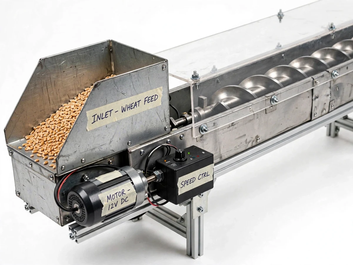
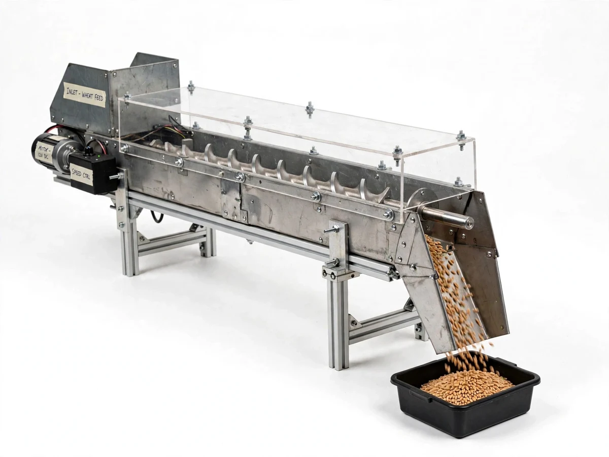
Screw conveyors move grain, cement, plastic granules and food powders through thousands of plants, yet mechanical students usually meet them only as a formula — throughput equals a constant times diameter squared times pitch times speed. This project makes the formula tangible: a bench-scale screw conveyor with a fabricated helical screw in a sheet-metal trough (transparent acrylic top so the material flow is visible), an inlet hopper, a discharge chute and a geared DC motor with a speed controller. The student loads wheat, rice or plastic granules, runs timed conveying trials at several speeds and two inclinations, weighs the discharged material, and compares the measured throughput with the theoretical capacity calculated from the screw's geometry. The gap between theory and measurement — slip, fill efficiency, inclination losses — becomes the most viva-worthy part of the report, and every number in it is the student's own.
How it works
- Fill the hopper with the test material (wheat, rice or granules) and set the trough to horizontal.
- Set a screw speed on the controller and measure the actual RPM with the tachometer sticker reading.
- Start the conveyor and, once flow is steady, collect the discharge in the bin for a timed 60-second interval.
- Weigh the collected material and compute throughput in kg/h for that speed.
- Repeat across the speed range, then repeat the series at an inclined trough setting.
- Compute the theoretical capacity from the screw diameter, pitch, RPM and the material's bulk density, with the standard fill-factor and inclination corrections.
- Plot measured vs theoretical throughput, and discuss fill efficiency, slip and inclination losses from your own data.
Tech stack:
- Fabricated helical screw on shaft
- Sheet-metal trough with acrylic top cover
- Inlet hopper and discharge chute
- Geared DC motor with PWM speed controller
- Adjustable-inclination support frame
- Digital weighing scale and stopwatch
- Tachometer sticker for RPM check
- Test materials: wheat, rice, plastic granules
| Parameter | Value |
|---|---|
| Screw diameter | Approximately 100 mm (design target) |
| Screw length | Approximately 1.2 m (design target) |
| Pitch | Approximately 100 mm, standard pitch (design target) |
| Speed range | Approximately 30–120 RPM (expected, controller-set) |
| Inclination | 0–20° adjustable (design target) |
| Throughput | Student-measured by timed weighing; theoretical capacity computed from geometry |
| Drive | Geared DC motor, 12/24 V with PWM controller |
| Trough | Sheet metal with transparent acrylic top, approximately 1.4 m overall |
Project features
- [Fabricated helical screw] A true helical flight wound on a shaft — the defining component — sized to the trough with proper clearance for smooth conveying.
- [Transparent trough cover] An acrylic top on the sheet-metal trough makes the material bed and its movement visible during every trial.
- [Inlet hopper and discharge chute] A sheet-metal hopper gives uniform feed and the chute delivers into a weighing collection bin.
- [Geared motor with speed control] A geared DC motor with a PWM speed controller lets the student run the full speed range for the throughput trials.
- [Adjustable inclination] The trough tilts from horizontal to about 20°, so the student measures and reports the inclination penalty themselves.
- [Timed weighing procedure] A digital weighing scale and stopwatch turn each trial into a measured throughput point — no estimated figures.
- [Theory-vs-measured comparison] The report template computes theoretical capacity from screw geometry and places the student's measured points beside it.
- [Multiple test materials] Trials run on wheat, rice or plastic granules, showing how bulk density and particle shape shift the results.
What is included
- Fabricated screw conveyor: screw, trough, hopper, chute, frame
- Geared DC motor with PWM speed controller and power supply
- Digital weighing scale and stopwatch
- Collection bins
- Test material starter pack (grain/granules)
- Trial procedure and observation sheets (blank, for your readings)
- Project report PDF (bulk-handling theory, design, procedure)
- PPT presentation for final review
- Viva Q&A preparation document
Limitations & prerequisites
- Throughput figures are entirely student-measured; the theoretical capacity is a design calculation, and the report presents both without claiming either as the other.
- Fill efficiency and slip depend on the material — the student's wheat results will not match their granule results, which is the point of the comparison.
- The model handles dry, free-flowing granular materials only; sticky, wet or fibrous materials jam the screw.
- Capacity falls with inclination; the 20° setting is for demonstrating the penalty, not for rated duty.
- Screw-to-trough clearance is a fabrication tolerance — excessive clearance raises slip and the student reports it as a build observation.
Frequently Asked Questions
What does the student actually measure?
Throughput at each speed and inclination setting: timed 60-second discharge collections weighed on the digital scale, converted to kg/h. Every plotted point is a real weighing, and the observation sheets are blank until the student runs the trials.
How is theoretical capacity calculated?
From screw geometry: Q = 60 × (π/4) × D² × pitch × N × bulk density × fill factor × inclination factor. The report derives it step-by-step with the student's own screw dimensions.
Why do measured and theoretical values differ?
Slip between material and flights, incomplete fill at the feed, clearance leakage and inclination losses. Quantifying that gap from their own data is the core engineering result of the project.
Which materials can be conveyed?
Dry free-flowing granules: wheat, rice, plastic granules, sand. Wet, sticky or long-fibre materials are outside the model's scope.
What bulk-handling theory does the viva cover?
Screw conveyor geometry (standard vs short pitch), fill factor, the effect of inclination, bulk density vs particle density, and why screw conveyors suit short, controlled feeds rather than long hauls.
Is this project suitable for a final-year project?
Yes — for Mechanical Engineering. It is a working materials-handling machine with fabricated components, a designed drive, and an experiment where the student measures, calculates and reconciles theory with reality. Suitable for B.E./B.Tech final-year projects in Mechanical Engineering.
Components & software requirements
- Fabricated helical screw on shaft
- Sheet-metal trough with acrylic top cover
- Inlet hopper and discharge chute
- Geared DC motor with PWM speed controller
- Adjustable-inclination support frame
- Digital weighing scale and stopwatch
- Tachometer sticker for RPM check
- Test materials: wheat, rice, plastic granules
Delivery information
Built-to-order project. Delivery timeline is shared after order confirmation based on current queue.
Support terms
Complete documentation, setup guide, and viva preparation included. Support for setup and explanation provided.