
More project photos (2)
The problem
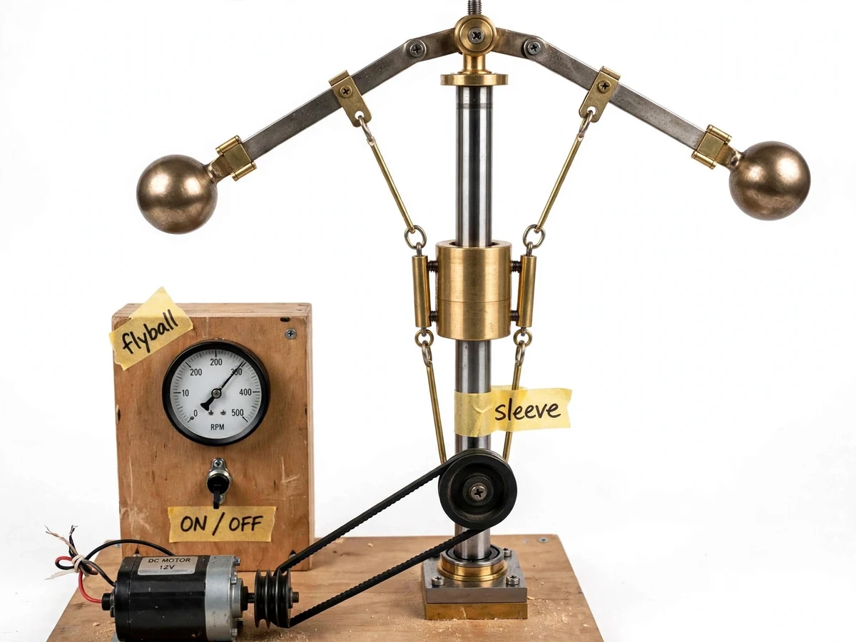
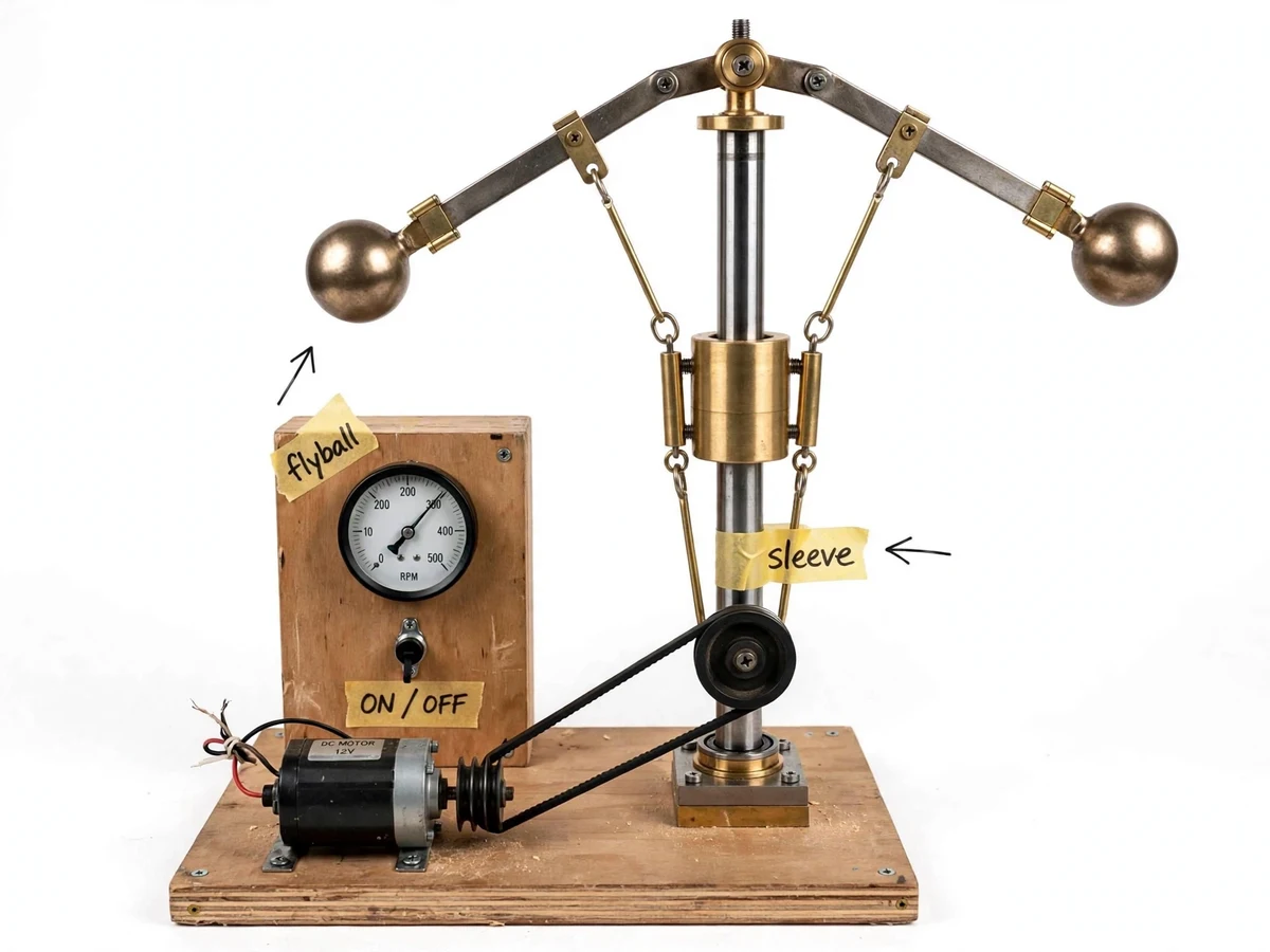
The centrifugal governor is the classic feedback device of mechanical engineering — the mechanism that kept steam engines at constant speed — yet students usually meet it only as a free-body diagram with rotating balls. A working model makes the theory physical: as the spindle spins faster, the flyballs swing outward and lift the sleeve, exactly the motion that would throttle an engine. This project builds that model on a wooden base with a 12 V DC motor, belt drive, speed regulator and a panel tachometer, so the student can set any speed, watch the sleeve respond, and measure the relationship between speed and sleeve lift. Swapping the control spring then shows how stiffness changes the governor's sensitivity — a genuine control-systems experiment on a purely mechanical device.
How it works
- The regulator is set to a low speed and the governor is switched on; the tachometer confirms the spindle speed once it steadies.
- The student reads the sleeve pointer position on its scale and records the speed–position pair.
- The speed is raised in steps across the tachometer range, with the sleeve position recorded at each steady speed — the flyballs visibly rise and the sleeve climbs.
- The recorded pairs are plotted as the governor characteristic curve (sleeve lift vs speed), and sensitivity is worked out from the curve's slope using the worksheet.
- The control spring is swapped for a stiffer (or softer) one and the sweep is repeated, showing how spring stiffness shifts the characteristic.
- The student compares the measured trend with the theoretical expectation from the procedure notes and writes up the comparison with the plotted curves.
Tech stack:
- Brass flyball and link assembly
- Sliding sleeve with pointer scale
- 12 V DC motor and belt drive
- Panel speed regulator
- 0-500 rpm dial tachometer
- Interchangeable spring set
- Wooden base and control panel fabrication
- Governor characteristic plotting procedure
| Parameter | Value |
|---|---|
| Governor type | Porter-type centrifugal (design) |
| Speed range | 0–500 rpm on panel tachometer (design) |
| Drive | 12 V DC motor with belt and pulleys (design) |
| Speed control | Panel regulator, continuous (design) |
| Sleeve readout | Pointer scale, 1 mm divisions (design) |
| Springs supplied | 3 stiffness grades (design set) |
| Base | Wooden base with control panel (design) |
| Power | 12 V DC adapter, approximately 2 A (expected) |
Project features
- [Flyball and spindle assembly] Two brass flyballs on pivoted arms, driven by the central spindle through the belt — the heart of the Porter-type mechanism.
- [Sliding sleeve] A brass sleeve that rides the spindle and is lifted by the flyball links, with a pointer scale to read its position at each speed.
- [DC motor with belt drive] A 12 V DC motor drives the spindle through a belt and pulleys, isolating motor vibration from the governor head.
- [Speed regulator] A panel-mounted regulator varies the motor voltage so the student can sweep the full speed range smoothly.
- [Panel tachometer] A 0–500 rpm dial tachometer on the control panel shows the spindle speed for every reading.
- [Interchangeable spring set] Extra springs of different stiffness are supplied; swapping them changes the sleeve-lift characteristic the student plots.
- [Fabrication drawings] Dimensioned drawings of the spindle, arms, sleeve and base layout for the report's fabrication chapter.
- [Characteristic-plotting procedure] A step-by-step method for recording sleeve position vs speed, plotting the characteristic curve, and computing sensitivity from the student's own data.
What is included
- Fabricated centrifugal governor model (spindle, flyballs, sleeve, base)
- 12 V DC motor with belt drive and speed regulator
- Panel tachometer and control panel with ON/OFF switch
- Interchangeable spring set (3 grades)
- Dimensioned fabrication drawings
- Step-by-step characteristic-plotting procedure with worksheets
- Project report PDF (background, fabrication, test methodology, results format)
- PPT presentation for final review
- Viva Q&A preparation document (governor types, sensitivity, stability, sleeve-lift theory)
Limitations & prerequisites
- A demonstration model, not an engine-coupled governor — it shows the characteristic; it does not regulate a real load.
- Sleeve position is read by eye on a pointer scale (typical uncertainty around ±1 mm); friction in the sleeve adds hysteresis the student is asked to observe and report.
- The tachometer is a panel dial instrument; speed readings carry the usual dial-reading uncertainty of a few rpm.
- Belt slip at very low speeds can make the bottom of the range less steady — the procedure starts the sweep above the slip zone.
- No measured sensitivity or performance figures are claimed; every number in the report comes from the student's own plotted data.
Frequently Asked Questions
What does the sleeve movement actually demonstrate?
In a real engine, that sleeve motion would pull the throttle linkage — more speed, sleeve rises, fuel cut back. The model shows the sensing half of that feedback loop, which is the part the theory chapter analyses.
What is governor sensitivity, and how is it measured here?
Sensitivity is how much the sleeve moves for a given speed change — the slope of the plotted characteristic curve. The worksheet shows how to extract it from the student's own readings.
Why swap the springs?
The spring fights the flyballs' outward swing; a stiffer spring needs more speed for the same lift. Repeating the sweep with different springs gives three characteristics to compare in the report.
Is this a Watt, Porter or Hartnell governor?
The build follows the Porter arrangement (central weight/sleeve with flyballs); the report chapter explains how it differs from Watt and Hartnell types.
Can the model run continuously for a demo?
Yes — the DC motor and belt drive are rated for extended demonstration runs, and the control panel has a single ON/OFF switch for viva-day operation.
Is this project suitable for a final-year project?
Yes — for Mechanical Engineering programs. It combines mechanism fabrication, instrumentation, and control-theory verification, and the report is built on the student's own measured characteristic curves. Suitable for B.E./B.Tech final-year projects in Mechanical Engineering.
Components & software requirements
- Brass flyball and link assembly
- Sliding sleeve with pointer scale
- 12 V DC motor and belt drive
- Panel speed regulator
- 0-500 rpm dial tachometer
- Interchangeable spring set
- Wooden base and control panel fabrication
- Governor characteristic plotting procedure
Delivery information
Built-to-order project. Delivery timeline is shared after order confirmation based on current queue.
Support terms
Complete documentation, setup guide, and viva preparation included. Support for setup and explanation provided.