
More project photos (2)
The problem
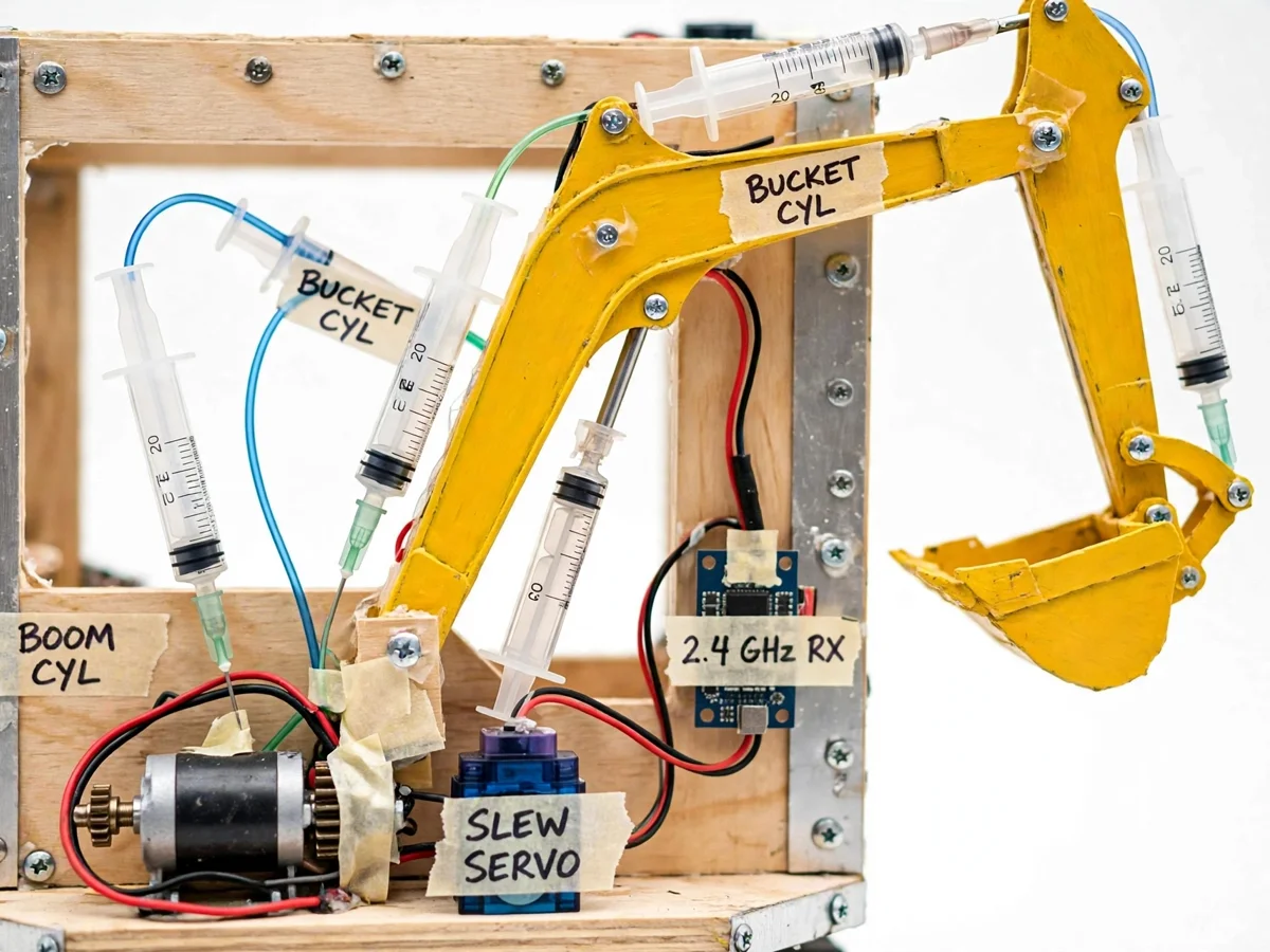
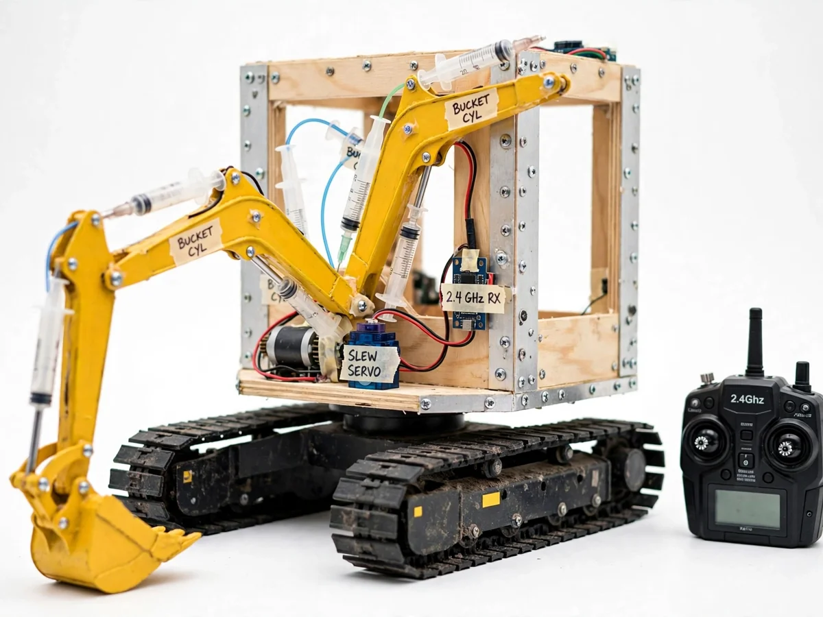
Real excavators are fluid-power machines, but most mechanical students first meet hydraulics as equations — Pascal's law, force multiplication, cylinder sizing — without ever feeling them work. This project closes that gap with a mini excavator that actually digs: a tracked undercarriage carries a rotating upper frame, and three paired syringe rams move the boom, arm and bucket through the full dig cycle (scoop, lift, slew, dump, return). Pushing water into one syringe extends its partner on the machine, so force transmission and displacement work exactly like a full-size hydraulic cylinder, at student-build cost. A 2.4 GHz proportional RC link controls track drive, slew and each ram, and the calibration procedure gives the student real stroke-versus-joint-angle data to present. Everything is fabricated from plywood and aluminium angle with ordinary fasteners, so the build process itself is defendable engineering.
Decodes 2.4 GHz proportional channels into drive signals for the tracks, slew drive and ram circuits.
Follow the working sequence
How it works
- The transmitter sends proportional channel commands over the 2.4 GHz link; the receiver decodes them into drive signals for the track motors, the slew drive and the three ram actuator circuits.
- Each hydraulic circuit is a paired set of 20 ml syringes joined by tubing: pushing fluid from the "master" syringe forces the "slave" syringe to extend, moving its cylinder pin and rotating the joint through the linkage.
- The boom ram anchors between the frame and the boom, the arm ram between boom and arm, and the bucket ram between arm and bucket — each joint angle is set by the volume of fluid displaced, exactly like oil in a real cylinder.
- The slew drive rotates the entire upper frame on its bearing relative to the track base, so the boom can be aimed anywhere within its approximately 200° arc (design target).
- Differential drive of the two track motors moves and steers the machine: both tracks together for forward/backward, opposite directions to skid-steer in place.
- A full dig cycle is demonstrated live: lower the boom, curl the bucket to scoop, lift, slew to the dump side, uncurl to empty, and return — all from the transmitter sticks.
- The student runs the calibration procedure: for each ram, syringe displacement is recorded against the measured joint angle, producing the stroke-angle tables that go into the report.
Tech stack:
- Plywood frame plates with aluminium angle and standard fasteners
- 20 ml plastic syringes with fluid tubing (paired master/slave rams)
- 2.4 GHz RC transmitter and receiver with proportional channels
- Servo-class slew drive and DC gear motors for the tracks
- 2S LiPo battery pack (7.4 V) with appropriate ESC/drive electronics
- Rubber caterpillar track sets on a steel roller frame
- Linkage geometry designed for the dig-cycle working envelope
- CAD-style fabrication drawings and assembly sequence
| Parameter | Value |
|---|---|
| Overall length (boom stowed) | Approximately 55 cm (design target) |
| Overall width across tracks | Approximately 30 cm (design target) |
| Overall height (boom raised) | Approximately 45 cm (design target) |
| Mass | Approximately 6 kg (design target) |
| Hydraulic rams | 3 pairs of 20 ml syringes (boom, arm, bucket) |
| Slew range | Approximately 200° (design target) |
| RC link | 2.4 GHz proportional, approx. 100 m line of sight (design target) |
| Track drive | 2 × DC gear motors, skid-steer differential |
| Battery | 2S LiPo, 7.4 V, approximately 2200 mAh (design target) |
| Bucket capacity | Approximately 250 ml of loose soil/sand simulant (design target) |
| Working reach | Approximately 60 cm from slew axis (design target) |
Project features
- [Syringe hydraulic actuation] Three paired syringe rams drive the boom, arm and bucket through genuine fluid displacement — pushing one syringe extends its partner, demonstrating Pascal's law with the same physics as full-size cylinders, at near-zero cost.
- [Tracked undercarriage] Twin rubber caterpillar tracks spread the machine's weight and keep it planted during dig cycles; differential track drive lets it skid-steer in place for tight demonstration setups.
- [Rotating upper frame] A slew bearing lets the upper frame rotate approximately 200° (design target) relative to the tracks, so the machine can dig, swing and dump to the side like the real thing.
- [2.4 GHz proportional RC control] One transmitter drives both track motors, the slew drive and all three hydraulic circuits proportionally, with a line-of-sight range of approximately 100 m (design target).
- [Student-fabricated structure] The frame is built from plywood plates and aluminium angle with ordinary screws and washers — no exotic tooling. Fabrication drawings document every cut so the student can explain the build in the viva.
- [Calibration procedure] The student measures cylinder stroke versus joint angle on their own build and records the data in the supplied calibration sheets — real numbers in the report, not textbook tables.
- [Optional: bucket load cell (extension)] A strain-gauge hook-up can log lifting force against ram displacement for students who want an instrumentation angle — documented as an optional extension, not part of the base build.
- [Future scope: closed-loop control] A future build could add position feedback on each joint for programmed dig cycles; the base machine ships as manual RC control.
What is included
- Fully assembled and tuned RC hydraulic excavator model (tracks, rotating frame, boom/arm/bucket, syringe rams, RC gear)
- 2.4 GHz RC transmitter bound to the receiver, tested for range
- Fabrication drawings and step-by-step assembly sequence
- Calibration procedure with blank stroke-angle record sheets
- Operating manual: battery care, bleeding air from the circuits, joint adjustment
- Project report PDF (fluid-power theory, linkage design, fabrication, calibration data)
- Abstract PDF (10-section)
- PPT presentation for final review
- Viva Q&A preparation document (Pascal's law, cylinder sizing, linkage geometry, RC control)
Limitations & prerequisites
- This is a demonstration model, not construction equipment: it is designed for loose soil, sand or simulant material in a shallow test bed, not compacted earth or rock — the student measures its real working loads rather than claiming production capability.
- Syringe rams leak and wear over time; the manual documents re-bleeding and syringe replacement as routine maintenance, and seals need periodic attention.
- Rubber tracks perform best on flat, firm surfaces; mud, steep slopes and water are outside the operating envelope.
- The 2.4 GHz link needs line of sight; walls, metal structures and heavy interference shorten the effective range.
- Run time per charge is limited (approximately 20–30 minutes of continuous demonstration, design target) — plan demo sessions accordingly.
- The base build is manual RC control only; programmed or autonomous dig cycles are future scope, not included.
- Dimensions, forces and ranges are design targets validated during build, not guaranteed datasheet values.
Frequently Asked Questions
How do the syringes actually drive the machine?
Each circuit pairs two 20 ml syringes connected by tubing, with the "slave" syringe pinned across a joint. When the master syringe is driven, water pressure extends the slave exactly like oil in a hydraulic cylinder — displacement in, displacement out. It is the same physics (Pascal's law) at toy scale, which is why it makes such strong viva material.
Is it strong enough to dig real soil?
It is designed to dig in loose soil, sand or prepared test-bed material with a bucket load of approximately 250 ml (design target). Compacted earth and rock are outside its envelope — and the project is honest about that: the calibration sheets record the real measured working loads from the student's own build.
What controls it and how far does it reach?
A 2.4 GHz proportional RC transmitter with one channel per function (two track motors, slew, three rams), bound and range-tested before dispatch, with a design-target range of approximately 100 m line of sight.
What does the student build versus what arrives?
The project arrives built-to-order as a complete working machine with fabrication drawings, so the student studies the build process. The student's own engineering work is the calibration: measuring stroke-versus-angle data, documenting the linkage geometry and presenting the dig cycle and maintenance procedure in the viva.
What maintenance does it need?
Routine syringe maintenance — checking for air in the lines, re-bleeding circuits, and replacing syringes as seals wear — plus track tension checks and battery care. The operating manual documents all of it, and knowing the maintenance procedure is itself good viva material.
Is this project suitable for a final-year project?
Yes — for Mechanical, Mechatronics and Robotics programs. It delivers genuine fluid-power behavior through syringe hydraulics, linkage design with real kinematics, RC control integration and a structured calibration exercise — a working machine the student demonstrates live, backed by measured data.
Components & software requirements
- Plywood frame plates with aluminium angle and standard fasteners
- 20 ml plastic syringes with fluid tubing (paired master/slave rams)
- 2.4 GHz RC transmitter and receiver with proportional channels
- Servo-class slew drive and DC gear motors for the tracks
- 2S LiPo battery pack (7.4 V) with appropriate ESC/drive electronics
- Rubber caterpillar track sets on a steel roller frame
- Linkage geometry designed for the dig-cycle working envelope
- CAD-style fabrication drawings and assembly sequence
Delivery information
Built-to-order project. Delivery timeline is shared after order confirmation based on current queue.
Support terms
Complete documentation, setup guide, and viva preparation included. Support for setup and explanation provided.
Download free synopsis (PDF)
Enter your name and WhatsApp number — the synopsis PDF downloads immediately. We may send occasional project updates on WhatsApp; no spam.