
More project photos (2)
The problem
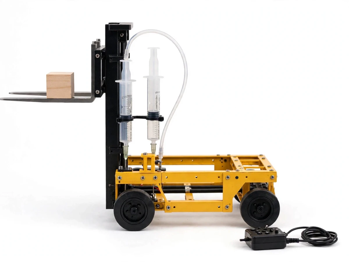
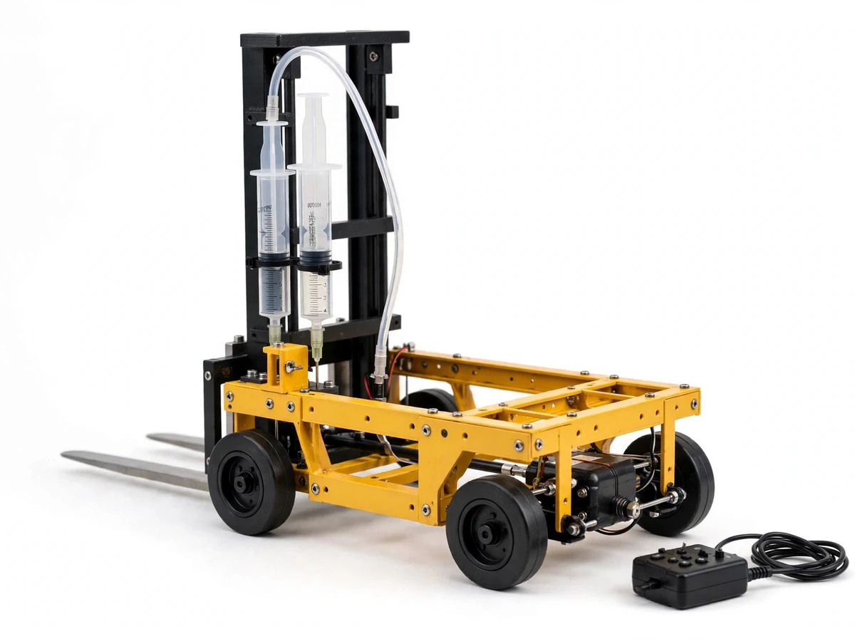
A mini forklift model with hydraulic lift and steering is a small tabletop machine that copies the working cycle of a real forklift: it drives up to a load, slides its forks underneath, raises the load on a mast, steers to a new position, and sets the load down. Warehouses and workshops move palletised goods this way daily, yet the machines themselves are large, expensive and impossible to bring into a classroom or a review room for a demonstration. Students studying mechanisms, hydraulics and vehicle control need a model that shows the same sequence — approach, lift, travel, place — in a form that fits on a table, runs on a battery supply, and can be stopped, inspected and repeated at any point in the cycle. This build answers that need with a wheeled chassis, a servo-steered front axle, a mast with a sliding fork carriage, and a syringe-based hydraulic lift worked from a wired hand controller.
| Setup | Drive and steering | Lift method | What it demonstrates |
|---|---|---|---|
| This model | DC gear-motor drive · servo steering | Water-filled syringes linked by tubing driving the fork carriage | The full cycle: drive, steer, lift, carry and place |
| Static forklift display model | No drive · no steering | Fixed forks at one height | Shape only · no working cycle to test or repeat |
| Remote-control car with no lift | Motor drive · steering | No forks · no lift | Travel only · nothing picked up, raised or set down |
The problem this model addresses is practical rather than theoretical. Textbook diagrams of forklift operation show the mast, the forks and the load path, but a diagram cannot show how much care the approach takes, how the load must sit centred on the forks, or how a small steering error at the start becomes a missed placement at the end. A static display model is no better: it has the right silhouette and none of the behaviour. The working model closes that gap by making the whole cycle observable. An operator drives the model to a small block, lowers the forks to floor level, slides them under the block, raises the carriage with the syringe lift, steers around a simple marked course, and lowers the block onto a target square. Every stage can be paused and discussed, and every failure — a fork missing the block, a load sliding off-centre, a turn taken too wide — is visible and instructive rather than hidden inside a diagram.
Wired hand controller with separate drive, steering, and lift controls.
Follow the working sequence
How it works
The end-to-end mechanism runs from the operator's hand to the placed load in four linked stages. The operator drives the model forward or in reverse with the gear motors, approaching the load slowly so the forks line up with it. Steering comes next: the servo turns the steered axle through its linkage, curving the model's path around the marked course toward the target square. Lifting follows the approach: pressing the control syringe forces water through the tubing into the lift syringe, which extends and pushes the fork carriage up the mast rails, raising the forks and the load together. Finally, the operator drives to the target square and releases the control syringe, letting the carriage descend until the load rests on the target, then reverses the model clear of the placed load.
- The builder assembles the chassis and fits the gear motors, wheels, steered axle, servo and steering linkage, checking that the steered wheels turn freely in both directions before the mast is fitted.
- The builder mounts the mast and the fork carriage, aligning the mast rails parallel so the carriage slides up and down without binding, and fits the two steel forks level with each other.
- The builder mounts the lift syringe on the chassis and the control syringe on the hand controller, joins them with tubing, fills the lines with water, and bleeds all air from the lines before the first lift.
- The builder wires the gear motors and the servo to the hand controller and the battery supply, then tests drive forward and reverse and steering left and right with the forks empty.
- For the lifting demonstration, the builder drives the model to a small block, lowers the forks to floor level, slides them under the block, and raises the carriage with the control syringe.
- For the placement test, the builder steers the loaded model around the marked course to the target square, lowers the load onto the target, and reverses the model clear.
- The builder writes up the results honestly, including the bleeding procedure, the load limit, the steering behaviour on the course, and every condition under which the lift should not be trusted.
Tech stack:
- DC gear motors · wheeled drive forward and reverse
- Servo motor · steered axle control through a linkage
- Plastic syringes and tubing · water-based hydraulic lift
- Steel forks and mast rails · sliding fork carriage
- Wired hand controller · drive, steering and lift controls
- Battery supply · bench power for motors and servo
- Chassis frame and wheels · tabletop model body
- Marked floor layout · pick-up and target squares for the placement test
| Parameter | Value |
|---|---|
| Build type | Tabletop hardware demonstration model · wheeled forklift with mast and forks (design target) |
| Model class | Demonstration model only · not an industrial forklift · not for real warehouse loads (design target) |
| Lift mechanism | Two water-filled syringes linked by tubing · control syringe plus lift syringe (design target) |
| Lift capacity | Approximately 500 g maximum load on the forks (design target) |
| Lift height | Approximately 20 cm maximum fork rise above floor level (design target) |
| Drive | DC gear motors · forward and reverse · slow bench speed (design target) |
| Drive speed | Approximately 0.15 m per second maximum on a flat bench surface (design target) |
| Steering | Servo motor · steered axle through a mechanical linkage (design target) |
| Forks | Two steel forks · level pair · sliding carriage on parallel mast rails (design target) |
| Power supply | Small battery supply · bench use only (design target) |
| Controller | Wired hand controller · separate drive, steering and lift controls (design target) |
| Test course | Marked floor layout · one pick-up square plus one target square (design target) |
| Builder note | On the bench build, air left in the syringe lines made the first lift spongy and uneven, so the lines are bled until only water moves before any demonstration, and a fork carriage that binds on the mast is traced to rails that are not parallel, so rail alignment is checked before the lift is blamed (builder observation) |
Project features
The model combines four capabilities that together reproduce the forklift working cycle at bench scale. First, the syringe-based hydraulic lift raises and lowers the fork carriage smoothly by water pressure, so the lift itself is a visible hydraulics lesson rather than a hidden motor. Second, servo steering turns the front axle through a linkage, giving the model a genuine turning circle and a steering behaviour that can be tested on a marked course. Third, DC gear-motor drive moves the model forward and in reverse at a slow, controllable bench speed, so the approach to a load can be made carefully rather than rushed. Fourth, the fork carriage slides on parallel mast rails and carries a small load, which lets the demonstration end with a real placement: a block picked up from one square and set down on another.
- [Syringe-based hydraulic lift] Pressing the control syringe pushes water through tubing into the lift syringe, extending it and raising the fork carriage on the mast, while releasing it lowers the carriage again under control — implemented in the base build.
- [Servo steering with linkage] A servo turns the steered axle through a simple mechanical linkage, so the model follows a steered path around a marked course instead of travelling in a straight line only — implemented in the base build.
- [DC gear-motor drive] Gear motors drive the wheels forward and in reverse at a slow bench speed, giving the operator fine control during the approach to a load — implemented in the base build.
- [Sliding fork carriage on a mast] The fork carriage rides on parallel mast rails and carries the load, so lifting keeps the forks level and the load stable through the raise and the carry — implemented in the base build.
- [Wired hand controller] A hand-held controller with separate controls for drive, steering and lift keeps every function under the operator's direct command, with no pairing or signal setup before a demonstration — implemented in the base build.
- [Load-placement test course] A marked floor layout with a pick-up square and a target square turns the demonstration into a repeatable test: pick up, travel, steer, and place, with success visible at a glance — implemented in the base build.
- [Wireless remote control] Future scope only, not implemented: replacing the wired controller with a wireless link is an extension with its own range and interference testing, not a feature the base build claims.
What is included
- Complete fabricated tabletop forklift model (chassis, mast, fork carriage, steel forks, syringe hydraulics, gear-motor drive, servo steering, wired hand controller, battery supply)
- Marked floor layout for the placement test (pick-up square and target square)
- Setup and testing guide (syringe bleeding procedure, rail-alignment check, drive and steering checks, placement-test procedure, load-limit notes)
- Project report PDF (mechanism background, hydraulics principle, build procedure, demonstration procedure, honest load and safety observations)
- PPT presentation for final review
- Viva Q&A preparation document (hydraulic pressure transmission, servo steering linkage, gear-motor drive, mast and carriage design, demonstration limits)
Limitations & prerequisites
- Tabletop demonstration only: this is a small bench model, not an industrial forklift, and it must never be presented as warehouse equipment or used with real pallets or heavy goods.
- Load limit is strict: the fork load must stay at or below approximately 500 g (design target), because a heavier load can stall the lift, tip the model forward, or bend the fork carriage.
- Water-based hydraulics only: the syringes and tubing carry water at low pressure, so leaks are possible at joints, and the model must be run over a tray or a wipeable surface with the lines checked before each demonstration.
- Slow bench speed only: the drive speed of approximately 0.15 m per second (design target) suits a careful bench approach and cannot keep up with, or stand in for, any real vehicle movement.
- Steering needs a flat surface: the steered axle and small wheels work on a flat bench or floor layout, and rough or uneven ground will skew the steering and the placement test.
- Supervision required during demonstrations: the moving forks and the load can pinch fingers, so the model is operated with hands clear of the mast and carriage, and the whole unit is an academic prototype, not a certified product.
Frequently Asked Questions
Is this project suitable for a final-year project?
Yes, for Mechanical programs, because it combines mechanism design, low-pressure hydraulics, steering linkage geometry and a repeatable placement test in one working model that a review panel can challenge directly. It gives a clear review thread: how water pressure in the syringes raises the carriage, how the servo linkage steers the axle, how the mast rails keep the forks level, and where a tabletop model honestly stops. The demonstration is the evidence, since the pick-up, carry and placement can be repeated on the spot.
How does the syringe hydraulic lift work?
By pressure transmission through water: pressing the control syringe forces water through the tubing into the lift syringe, and because water barely compresses, the lift syringe extends by nearly the same volume and pushes the fork carriage up the mast rails. Releasing the control syringe lets water return, so the carriage descends under control rather than dropping. The lift is smooth and visible, which is why it suits a classroom demonstration, and the lines must be bled of air first, since trapped air compresses and makes the lift spongy.
How does the steering work?
Through a servo and a mechanical linkage: the servo turns a horn that pushes and pulls the steering linkage, which angles the steered wheels together so the model curves instead of travelling straight. The operator steers from the wired hand controller while driving, which makes the marked-course test a genuine steering exercise rather than a straight-line run. Steering geometry is kept simple on purpose, so the linkage can be inspected, measured and explained during a review.
What can the model lift, and what must it never lift?
It lifts small bench loads up to approximately 500 g (design target), such as a small wooden block or a light model parcel placed centrally on the forks. It must never lift real warehouse goods, tools, books beyond the limit, or anything a person could be hurt by if it fell, because the model is a tabletop demonstrator with a light chassis and low-pressure water hydraulics. Overloading risks stalling the lift, tipping the model forward, or bending the carriage, so the limit is stated in the report and on the demonstration notes.
Why is the controller wired instead of wireless?
Because a wired controller keeps every function under direct command with no pairing, signal loss or interference to explain away during a demonstration. The base build uses a hand-held wired controller with separate drive, steering and lift controls, so a review demonstration starts the moment the battery is connected. A wireless link is listed as future scope only, since it would need its own range and interference testing before it could be claimed as part of the build.
What goes wrong most often, and how is it fixed?
Air trapped in the syringe lines and a binding fork carriage are the two common faults, and both have simple fixes that belong in the demonstration notes. Air makes the lift spongy and uneven, and it is fixed by bleeding the lines until only water moves before the first lift. A carriage that sticks or tilts is usually traced to mast rails that are not parallel, and it is fixed by realigning the rails rather than forcing the carriage or blaming the hydraulics.
Components & software requirements
- DC gear motors · wheeled drive forward and reverse
- Servo motor · steered axle control through a linkage
- Plastic syringes and tubing · water-based hydraulic lift
- Steel forks and mast rails · sliding fork carriage
- Wired hand controller · drive, steering and lift controls
- Battery supply · bench power for motors and servo
- Chassis frame and wheels · tabletop model body
- Marked floor layout · pick-up and target squares for the placement test
Delivery information
Built-to-order project. Delivery timeline is shared after order confirmation based on current queue.
Support terms
Complete documentation, setup guide, and viva preparation included. Support for setup and explanation provided.
Download free synopsis (PDF)
Enter your name and WhatsApp number — the synopsis PDF downloads immediately. We may send occasional project updates on WhatsApp; no spam.