
More project photos (2)
The problem
The Scotch yoke appears in almost every theory-of-machines syllabus, yet students usually meet it only as a diagram: a crank, a slotted block and a slider that somehow produces sinusoidal motion. The kinematics are elegant — the horizontal displacement follows x = r·cos(θ) exactly — but the diagram hides the practical details that matter in a workshop: how the pin stays engaged in the slot, how the yoke is constrained so it cannot rotate, how backlash between pin and slot distorts the "perfect" sine wave, and what torque the motor actually needs. A physical model makes all of this visible and measurable. Students can change the crank radius, count strokes per minute, time a cycle against the theoretical value, and watch the slider reach maximum velocity at mid-stroke and zero velocity at the dead centres — the signature of simple harmonic motion. This project delivers that model as a built-to-order mechanical prototype, with the fabrication drawings and kinematic calculations documented so the student can genuinely defend every design decision.
How it works
- The 12 V DC geared motor drives the crank wheel through a direct shaft coupling at approximately 60 RPM (speed adjustable via the PWM controller).
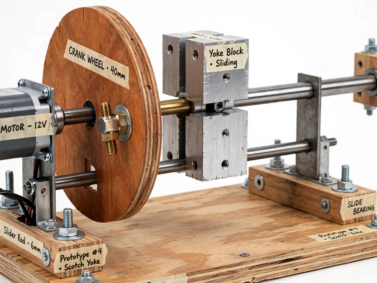
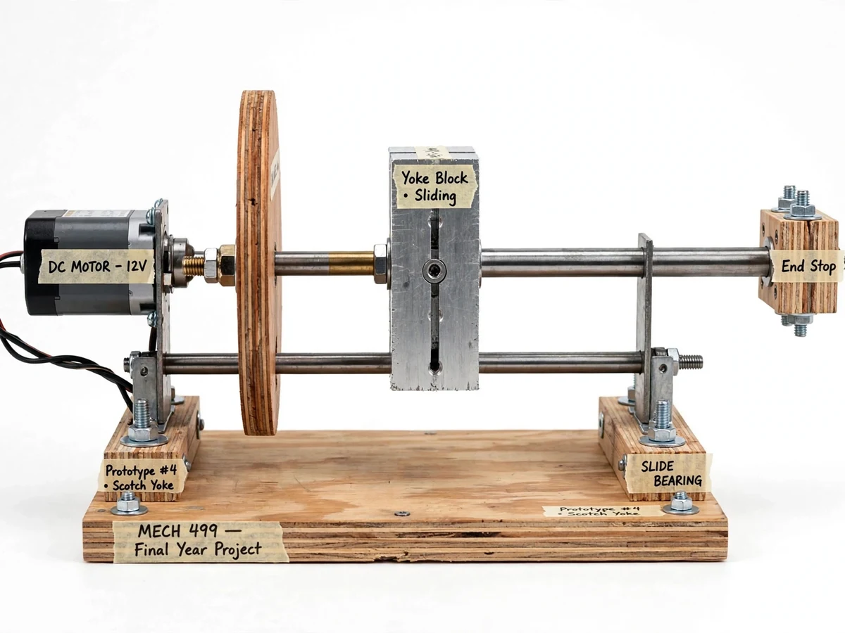
- A brass crank pin fixed at a set radius on the wheel face engages the vertical slot machined into the yoke block.
- As the wheel turns, the pin's horizontal motion component pushes the yoke block left and right, while its vertical component slides harmlessly along the slot.
- The yoke block, bolted to the horizontal slider rod and constrained by the twin guide rods, can move only along the slider axis.
- The result is sinusoidal reciprocating motion: displacement x = r·cos(θ), with maximum velocity at mid-stroke and zero velocity at the two dead centres.
- Moving the crank pin to the 20, 30 or 40 mm hole changes the stroke to 40, 60 or 80 mm; the graduated scale confirms each setting during measurement.
Tech stack:
- Mild steel (yoke block, brackets, fasteners)
- Plywood (base board, crank wheel)
- 12 V DC geared motor · PWM speed controller
- Brass crank pin
- Polished steel guide rods (Ø8 mm)
- 608-ZZ ball bearings (crank shaft support)
- Hand tools & workshop fabrication: drilling, tapping, filing, sawing
- Kinematic calculation sheet (SHM displacement/velocity/acceleration)
| Parameter | Value |
|---|---|
| Mechanism type | Scotch yoke — rotary to reciprocating (design) |
| Crank radius settings | 20, 30, 40 mm (configurable via pin holes) |
| Stroke length | 40, 60, 80 mm (2 × crank radius, calculated) |
| Crank wheel diameter | Approximately 120 mm (design) |
| Drive | 12 V DC geared motor, approximately 60 RPM (design target) |
| Cycle rate | Approximately 60 full cycles/min at full speed (calculated) |
| Max slider velocity | Approximately 0.25 m/s at 40 mm radius, 60 RPM (calculated from SHM) |
| Slider rod | Ø8 mm polished steel, approximately 300 mm long |
| Base | Plywood, approximately 450 × 200 × 18 mm |
| Power | 12 V DC, approximately 1 A (design target) |
| Overall footprint | Approximately 450 × 200 × 220 mm (design) |
Project features
- [Working Scotch yoke mechanism] Crank wheel, crank pin, slotted yoke block and guided slider rod assembled on a rigid base — one revolution of the crank produces one full back-and-forth cycle of true simple-harmonic motion.
- [Adjustable crank radius] Three pin positions on the crank wheel (20, 30 and 40 mm radii) change the stroke length from 40 to 80 mm, so students can verify the stroke = 2 × crank radius relationship experimentally.
- [Motorised drive with speed control] A 12 V DC geared motor (approximately 60 RPM) with a PWM speed controller runs the mechanism continuously for demonstrations and timing measurements.
- [Motion-timing chart] A printed chart maps crank angle to slider displacement, velocity and acceleration — derived from the SHM equations — so measured stroke timing can be compared against theory.
- [Constrained yoke slide] The yoke block rides on twin polished guide rods through slide-bearing blocks, keeping the motion strictly linear and the slot-pin contact visible from the side.
- [Graduated stroke scale] A ruler scale fixed along the slider travel lets students read stroke length directly at each crank-radius setting during the viva demo.
- [Dimensioned fabrication drawings] 2D drawings of every part — crank wheel, yoke block, base, bearing blocks — with dimensions, hole positions and a fastener list, suitable for a workshop file.
What is included
- Fully assembled and tested Scotch yoke demonstration model
- Dimensioned fabrication drawings (2D, printable) with fastener and material list
- Kinematic calculation sheet: SHM equations, velocity/acceleration curves for each radius setting
- Motion-timing chart mapping crank angle to displacement
- Project report PDF (background, theory of machines, design calculations, fabrication steps, observation tables)
- PPT presentation for final review
- Viva Q&A preparation document (SHM derivation, inversions, applications, comparison with slider-crank)
- Bill of materials with approximate sourcing costs
Limitations & prerequisites
- Demonstration model only — it is not rated for driving any external load; the slider rod carries the yoke alone.
- The yoke slot and crank pin are hand-fabricated, so a small clearance exists; expect minor backlash versus the ideal sine curve.
- Maximum speed is set by the geared motor (approximately 60 RPM); it cannot demonstrate high-speed dynamic effects.
- Wooden parts are sensitive to moisture and rough handling — store the model dry and transport it carefully.
- No instrumentation is built in: stroke timing is measured manually with a stopwatch and the printed scale.
- Sustained running at full speed warms the small DC motor; limit continuous demo runs to about 10 minutes with cool-down gaps.
Frequently Asked Questions
How does a Scotch yoke differ from a slider-crank?
Both convert rotation to reciprocating motion, but the Scotch yoke's slotted guide forces the slider to follow x = r·cos(θ) exactly — pure simple harmonic motion — while a slider-crank's connecting rod introduces a small distortion from true SHM. The model makes this comparison concrete during the viva.
Can the stroke length be changed?
Yes. The crank wheel has three pin holes at 20, 30 and 40 mm radii, giving strokes of 40, 60 and 80 mm. Loosening one nut and shifting the pin takes under a minute, and the graduated scale confirms the new stroke immediately.
What measurements can a student take with this model?
Stroke length at each pin setting, cycles per minute at a given PWM setting, time per cycle versus the theoretical 1 s at 60 RPM, and mid-stroke versus dead-centre velocity behaviour — all recorded in the observation tables of the report.
Where are Scotch yoke mechanisms used in practice?
In small steam engines and pumps, valve actuators, testing machines that need sinusoidal loading, and some compressor designs — anywhere a compact, exact-SHM reciprocating drive is useful without a connecting rod.
What maintenance does the model need?
Almost none: keep the guide rods clean and lightly oiled, check the crank-pin nut stays tight before each demo, and keep the plywood base dry. Spare fasteners are listed in the bill of materials.
Is this project suitable for a final-year project?
Yes — for Mechanical engineering programs. It covers theory-of-machines kinematics, design calculation, workshop fabrication and experimental verification in one tangible build. Suitable for B.E./B.Tech final-year projects in Mechanical.
Components & software requirements
- Mild steel (yoke block, brackets, fasteners)
- Plywood (base board, crank wheel)
- 12 V DC geared motor · PWM speed controller
- Brass crank pin
- Polished steel guide rods (Ø8 mm)
- 608-ZZ ball bearings (crank shaft support)
- Hand tools & workshop fabrication: drilling, tapping, filing, sawing
- Kinematic calculation sheet (SHM displacement/velocity/acceleration)
Delivery information
Built-to-order project. Delivery timeline is shared after order confirmation based on current queue.
Support terms
Complete documentation, setup guide, and viva preparation included. Support for setup and explanation provided.