
More project photos (2)
The problem
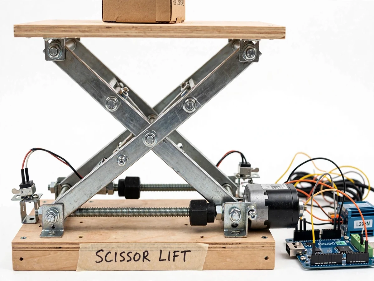
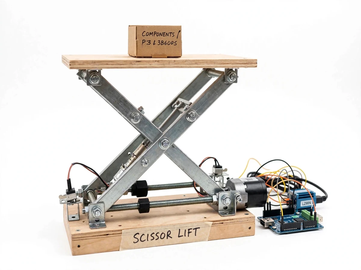
Scissor lifts are everywhere in industry — car service lifts, warehouse order pickers, aerial work platforms — because the scissor linkage turns a short horizontal actuator stroke into a large, stable vertical travel while keeping the platform level. The mechanism looks simple but its kinematics and force requirements are genuinely instructive: the force the actuator must provide changes with the lift angle, which is why real scissor lifts struggle most at the bottom of travel. This project builds a motorized working model of the mechanism: a 12 V DC geared motor drives a threaded screw rod through a nut block, the screw pulls the base of the scissor arms, limit switches cut travel at both ends, and an Arduino with an L298N driver provides up, down and stop control from push-buttons. The student gets a tangible platform for measuring mechanical advantage, lift speed versus load, and current draw at different heights.
How it works
- The student assembles the bolted scissor arms, base frame, wooden platform and the screw-drive subassembly (motor, coupling, threaded rod, nut block) following the assembly guide.
- Pressing the up button runs the motor one way; the nut block travels along the screw and pulls the base pivots of the scissor arms together, raising the platform.
- Pressing down reverses the motor; the nut block pushes the base pivots apart and the platform lowers under control.
- The limit switches cut the motor at the top and bottom of travel regardless of button state, and the emergency stop overrides everything.
- The student runs the load-test procedure: times the lift at several payloads, logs motor current with a clamp/multimeter, and records platform deflection.
- The measured data goes into the report's analysis section — force-vs-angle behavior, speed-vs-load curves and the measured self-locking hold.
Tech stack:
- 12 V DC geared motor with flexible coupling
- Threaded screw rod with nut block (lead-screw drive)
- Bolted steel scissor arms with pivot bushings
- Arduino Uno (ATmega328P) with L298N motor driver
- Microswitch limit switches (top and bottom of travel)
- Push-button station (up, down, emergency stop)
- C/C++ control firmware with debounce and interlocks
- 12 V bench supply / battery power
| Parameter | Value |
|---|---|
| Lowered height | Approximately 120 mm (design) |
| Raised height | Approximately 400 mm (design) |
| Platform | Approximately 300 x 200 mm plywood (design) |
| Design payload | Approximately 5 kg (design target) |
| Lift time (no load) | Approximately 15–20 s full travel (expected) |
| Motor | 12 V DC geared, approximately 30 rpm output (design) |
| Screw | Approximately 8 mm threaded rod, 1.25 mm pitch (design) |
| Power | 12 V DC, approximately 2 A max draw (expected) |
Project features
- [Screw-driven scissor mechanism] A threaded screw rod and nut block convert the motor's rotation into the horizontal pull that opens and closes the scissor linkage — self-locking, so the platform holds position with no power.
- [Geared 12 V DC drive] A high-torque geared motor sized for the mechanism drives the screw through a flexible coupling, with current draw low enough to run from a bench supply or battery.
- [Limit-switch travel protection] Microswitches at both ends of travel stop the motor automatically, preventing mechanical over-travel in both directions.
- [Arduino push-button control] Up, down and emergency-stop push-buttons are handled in firmware with debounce and direction interlocking, so up and down can never be driven together.
- [Self-locking hold] The screw drive is inherently self-locking: release the button and the platform stays exactly where it is — a key scissor-lift property the student can demonstrate.
- [Load-test procedure] A documented procedure measures lift time, motor current and platform deflection at several payloads, giving the report real measured data.
- [Adjustable geometry] The scissor arms are bolted, not welded, so the student can vary pivot spacing and repeat the mechanical-advantage experiment at different geometries.
What is included
- Working motorized scissor lift model (mechanism, drive, electronics)
- Arduino control firmware with interlocked up/down/stop logic
- Load-test and measurement procedure document
- Mechanical assembly guide with drawings and bill of materials
- Project report PDF (scissor kinematics, force analysis, measured results procedure)
- PPT presentation for final review
- Viva Q&A preparation document (mechanical advantage, screw self-locking, limit logic)
Limitations & prerequisites
- A scale working model, not an industrial lift — the 5 kg design payload must not be exceeded, and no person may ride it.
- The threaded-rod drive is slow by design (approximately 15–20 s full travel); it demonstrates the mechanism, not high-speed lifting.
- Platform deflection is expected at full payload; the test procedure measures and reports it rather than claiming rigidity.
- The screw and nut need occasional light greasing; running dry accelerates wear and increases current draw.
- Outdoor or dusty use is not intended — the mechanism and electronics are indoor lab equipment.
- Battery is not included as standard; the model ships with a 12 V DC input jack for a bench supply or the student's own pack.
Frequently Asked Questions
Why use a screw drive instead of a hydraulic cylinder?
A screw is cheap, safe at student scale, and self-locking — the platform holds position with no power. It also makes the mechanical-advantage story measurable, since the student can compute the expected force from the screw pitch.
How does the platform stay level while lifting?
The scissor linkage is symmetric: both sides open and close together, and the platform mounts ride in slots at the top pivots, so the deck stays horizontal through the full travel.
What stops the mechanism from over-travelling?
Microswitch limit switches at the top and bottom of travel cut the motor in firmware, plus a redundant mechanical stop. The emergency stop button overrides everything.
What real data can the report include?
Lift time vs payload, motor current vs lift height, and platform deflection at the design payload — all from the included load-test procedure, measured by the student on their own build.
Can the geometry be changed for experiments?
Yes — the arms are bolted, so the student can vary the pivot spacing or arm count and repeat the measurements, which makes a strong experimental chapter.
Is this project suitable for a final-year project?
Yes — for Mechanical and Mechatronics programs. It combines mechanism design, actuation, control logic and experimental measurement in one build. Suitable for B.E./B.Tech final-year projects in Mechanical and Mechatronics.
Components & software requirements
- 12 V DC geared motor with flexible coupling
- Threaded screw rod with nut block (lead-screw drive)
- Bolted steel scissor arms with pivot bushings
- Arduino Uno (ATmega328P) with L298N motor driver
- Microswitch limit switches (top and bottom of travel)
- Push-button station (up, down, emergency stop)
- C/C++ control firmware with debounce and interlocks
- 12 V bench supply / battery power
Delivery information
Built-to-order project. Delivery timeline is shared after order confirmation based on current queue.
Support terms
Complete documentation, setup guide, and viva preparation included. Support for setup and explanation provided.