
More project photos (2)
The problem
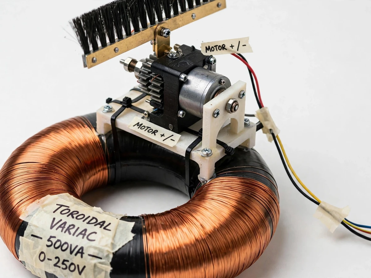
Mains voltage in many areas swings well outside the nominal 230 V, stressing appliances, lab equipment and anything with a motor or transformer inside. The classic industrial answer is the servo stabilizer: a motor-driven autotransformer whose brush is moved until the output is correct — smooth, stepless correction, unlike relay tap-changers that jump in coarse steps. This project builds that servo loop at bench scale and makes it a control-systems teaching instrument: the sensing, the comparison against a setpoint, the motor actuation and the deadband that prevents oscillation are all visible and explainable. Three preset buttons (220/230/240 V) turn it into a practical bench AC source as well as a feedback-theory demonstrator.
How it works
- The variac output is stepped down by a sensing transformer, rectified, and scaled to the Arduino's ADC range for measurement.
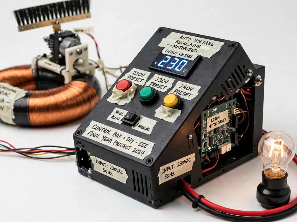
- The firmware compares the measured voltage with the active preset (220, 230 or 240 V selected by push-button).
- If the output is below the setpoint minus the deadband, the Arduino drives the L298N motor driver forward; above the setpoint plus the deadband, it reverses.
- Inside the ±2 V deadband the motor stops, holding the brush position without hunting.
- Limit switches at both ends of travel open the drive path if the brush ever reaches the mechanism's limits.
- The digital meter shows the corrected output live while the lamp load demonstrates stable brightness as the input voltage is varied with an external source.
Tech stack:
- Toroidal autotransformer (variac), 0–250 V, 500 VA
- 12 V DC gear motor with reduction gearing
- Arduino Uno (ATmega328P)
- L298N dual H-bridge motor driver
- Sensing transformer + rectifier + divider
- Digital AC voltmeter (panel instrument)
- Preset push-buttons, AUTO/MANUAL toggle, limit switches
| Parameter | Value |
|---|---|
| Variac rating | 0–250 V, 500 VA toroidal (design) |
| Output presets | 220 / 230 / 240 V, push-button selected |
| Regulation band | Approximately ±2 V around setpoint (design target) |
| Brush travel time | Approximately 3–5 s end to end (expected) |
| Motor | 12 V DC gear motor (datasheet) |
| Driver | L298N H-bridge (datasheet) |
| Protection | End-of-travel limit switches both directions |
| Display | Digital AC voltmeter, live output |
Project features
- [Closed-loop servo regulation] The Arduino reads the output voltage, compares it with the selected preset, and drives the variac brush toward the setpoint — a complete feedback loop on real mains voltage.
- [Three voltage presets] Push-buttons select 220, 230 or 240 V targets, covering the common nominal standards and making the setpoint change a one-press demo.
- [Deadband anti-hunt logic] The motor stops inside a ±2 V band around the setpoint, so the mechanism does not oscillate or chatter around the target.
- [Manual jog mode] An AUTO/MANUAL toggle hands brush control to jog buttons in both directions, useful for demonstrations and for parking the brush safely.
- [End-of-travel limit switches] Micro-switches at both ends of brush travel cut the motor drive, protecting the winding and the gear train from overrun.
- [Live output metering] A digital AC voltmeter displays the regulated output continuously, so correction is visible as the input is varied.
- [Demonstration load] A lamp load on the output shows regulation under load and gives the classic "dim/bright" visual as voltage is corrected.
What is included
- Fully wired regulator (variac, motor and gearing, control box, meter, lamp load)
- Arduino firmware implementing the servo loop (presets, deadband, jog, limits)
- Calibration procedure for the voltage-sensing stage
- Complete wiring diagram and schematic
- Servo-control theory notes for the report
- Project report PDF (background, feedback theory, methodology, calibration)
- PPT presentation for final review
- Viva Q&A preparation document (closed-loop control, deadband, variac vs tap-changer, limit protection)
Limitations & prerequisites
- Correction speed is limited by the gear-motor travel time (a few seconds end to end); it handles slow mains drift, not sub-cycle sags — fast sag correction needs electronic tap-switching, listed as future scope.
- The 500 VA variac rating bounds the demonstration load; the documentation states the safe load limit clearly.
- Mains wiring is involved: assembly, testing and any servicing must follow the documented safety procedure with faculty supervision.
- Regulation accuracy is a design target verified by the buyer-run calibration procedure, not a factory-measured claim.
- The prototype is a bench/lab instrument, not a certified voltage stabilizer for household use.
Frequently Asked Questions
How is this different from a relay-type voltage stabilizer?
Relay stabilizers switch transformer taps in discrete steps, so the output jumps. The motor-driven variac moves a brush continuously along the winding, giving smooth stepless correction — and this project shows that mechanism working under closed-loop control.
What does the deadband do?
Without it, the controller would drive the motor back and forth forever around the exact setpoint (hunting), wearing the mechanism. The ±2 V deadband tells the controller that "close enough" is good, so the motor rests once the output is inside the band.
Why three presets?
220, 230 and 240 V cover the nominal standards used across regions and let the demonstrator change the regulation target with one press, then watch the servo re-converge — a strong viva demonstration.
What happens at the ends of brush travel?
Limit switches cut the motor drive before the brush can overrun the winding or jam the gears. The firmware also refuses to drive further in the blocked direction until commanded the other way.
Can it correct a sudden voltage sag?
Only slow variations — the gear motor needs seconds for full travel. Fast electronic correction is a different technology (listed as future scope); the documentation is explicit about this boundary.
Is this project suitable for a final-year project?
Yes — for Electrical and Electronics engineering programs. It is one of the few student builds that demonstrates closed-loop control on real AC power, with clear theory-to-hardware mapping for the viva. Suitable for B.E./B.Tech final-year projects in Electrical and Electronics engineering.
Components & software requirements
- Toroidal autotransformer (variac), 0–250 V, 500 VA
- 12 V DC gear motor with reduction gearing
- Arduino Uno (ATmega328P)
- L298N dual H-bridge motor driver
- Sensing transformer + rectifier + divider
- Digital AC voltmeter (panel instrument)
- Preset push-buttons, AUTO/MANUAL toggle, limit switches
Delivery information
Built-to-order project. Delivery timeline is shared after order confirmation based on current queue.
Support terms
Complete documentation, setup guide, and viva preparation included. Support for setup and explanation provided.