
More project photos (3)
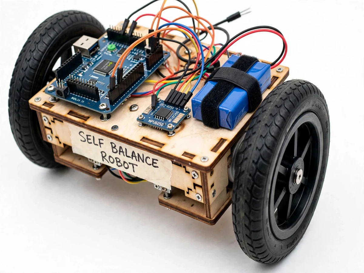
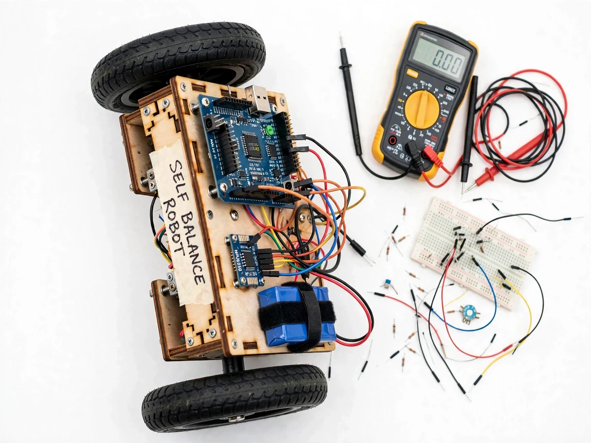
The problem
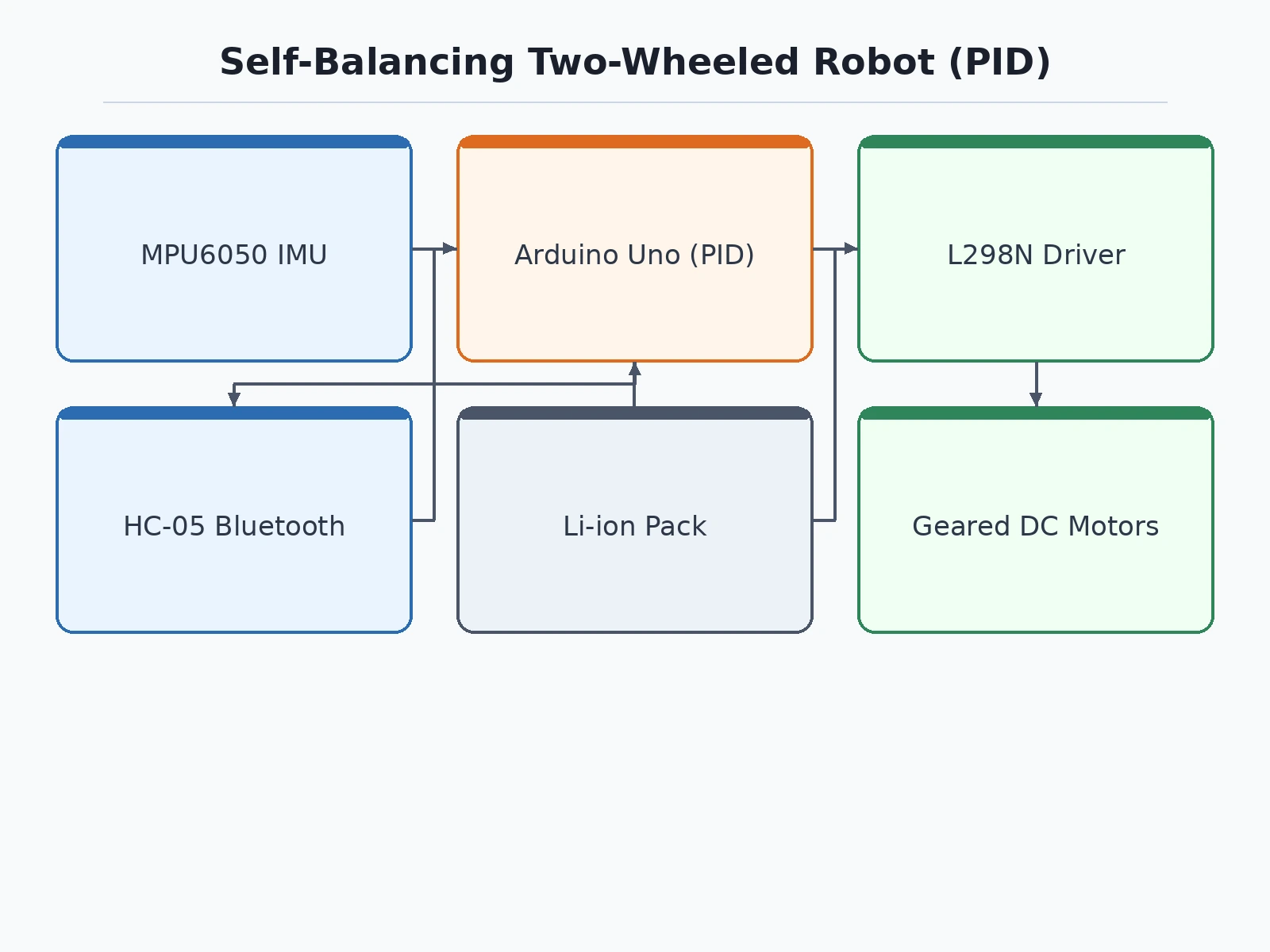
A self-balancing robot is an inverted pendulum on wheels: unlike a stable cart, its center of mass sits above its pivot, so it must constantly drive its wheels to stay upright — exactly the control problem behind Segway-style transporters and two-wheeled delivery bots. Students usually meet this system only as equations in a controls course, without ever closing the loop themselves, and the gap between the textbook PID formula and a robot that actually stands up is where most of the real learning happens. This project closes that gap with a student-built two-wheeled robot: an MPU6050 inertial sensor measures tilt at high rate, a complementary filter fuses accelerometer and gyroscope data into a clean angle estimate, and an Arduino runs a PID loop that drives two geared DC motors to hold the upright position. The gains are exposed for live tuning, so the student experiences overshoot, oscillation and sluggish response hands-on — and can defend every term of the control logic in a viva.
Measures tilt at high rate; a complementary filter fuses gyro and accelerometer into a stable angle.
Follow the working sequence
How it works
- The MPU6050 IMU is mounted on the chassis and zero-offset calibrated with the robot held upright, so the firmware reads tilt angle from a true zero.
- During operation the firmware samples the IMU, fuses accelerometer and gyroscope data with a complementary filter, and computes the tilt angle relative to vertical.
- The PID controller compares the measured angle with the upright setpoint and computes a corrective wheel command from the proportional, integral and derivative terms.
- The command is sent to the motor driver; the wheels drive into the fall direction, keeping the center of mass over the wheelbase.
- The student tunes Kp, Ki and Kd live over Bluetooth — starting with Kp only, adding Kd to damp oscillation, then Ki to remove steady lean — following the included procedure.
- Telemetry (angle, motor output, gains) streams continuously, so every tuning step is visible on the dashboard and can be captured for the report.
Tech stack:
- Arduino Uno (ATmega328P)
- MPU6050 6-axis IMU with complementary filter
- DC geared motors with quadrature encoders
- L298N / TB6612FNG motor driver
- PID control algorithm (C/C++ firmware)
- HC-05 Bluetooth module for telemetry
- 2S Li-ion battery pack with protection circuit
- Serial dashboard for live tuning and logging
| Parameter | Value |
|---|---|
| Wheel diameter | Approximately 65 mm (design) |
| Chassis | Laser-cut plywood, approximately 180 x 120 mm (design) |
| Control loop rate | Approximately 200 Hz (design target) |
| Tilt sensing | MPU6050, ±2 g / ±250 °/s ranges (datasheet) |
| Recovery range | Approximately ±10° from vertical (design target) |
| Battery | 2S Li-ion, approximately 2200 mAh (design) |
| Expected runtime | Approximately 30–45 min per charge (expected) |
| Overall weight | Approximately 800 g (design) |
Project features
- [PID control loop with live tuning] The Arduino runs a true PID controller on the tilt angle; Kp, Ki and Kd are adjustable at runtime over serial or Bluetooth, so overshoot, oscillation and settling can be explored hands-on.
- [MPU6050 tilt sensing with sensor fusion] A 6-axis IMU measures tilt at high rate; a complementary filter fuses gyroscope and accelerometer readings into a stable angle estimate, with a documented zero-offset calibration.
- [Geared DC motors with encoders] High-torque geared motors give the fast response a balance loop needs; encoder feedback supports optional velocity and position-hold extensions.
- [Bluetooth telemetry] Live tilt angle, PID output and gain values stream to a phone or laptop dashboard during tuning, so the student can see the loop responding in real time.
- [Push-recovery demonstration] The robot visibly fights to stay upright when gently pushed, making the control loop tangible in demos and review presentations.
- [Structured tuning procedure] A step-by-step method (Ziegler–Nichols style) takes the student from open-loop wobble to a stable, tuned balance — every step is documented for the report.
- [Battery management] A protected Li-ion pack with a low-voltage cutoff keeps the electronics safe during repeated tuning sessions.
What is included
- Working self-balancing robot prototype (chassis, motors, electronics, battery)
- Arduino firmware with PID loop, sensor fusion and Bluetooth telemetry
- Sensor-calibration and PID gain-tuning procedure document
- Wiring diagram and mechanical assembly guide
- Project report PDF (control theory, PID design, tuning results procedure)
- PPT presentation for final review
- Viva Q&A preparation document (inverted pendulum, PID terms, sensor fusion)
Limitations & prerequisites
- Balances only on flat, hard surfaces — slopes, carpets, ramps and stairs are out of scope.
- The loop is tuned for the shipped weight distribution; adding significant payload needs re-tuning.
- Balancing is a dynamic process: the robot needs room to roll forward and back, roughly a meter of clear floor.
- IMU zero-offset drifts with temperature; the calibration procedure must be repeated if the environment changes.
- Not a transport device — it carries no rider or heavy load and is not a Segway.
- Tuning is hands-on by nature; the procedure is documented but the student must perform it on their build.
Frequently Asked Questions
How does the robot actually stay upright?
It is an inverted pendulum: the IMU measures which way the robot is tipping, and the PID controller drives the wheels in that direction fast enough to keep the center of mass over the wheelbase. The loop runs about 200 times per second, which is what makes the correction feel instant.
Do I need to know control theory beforehand?
No. The included tuning procedure walks through each PID term with plain-language explanations and observable behavior (Kp too high causes wobble, Kd damps it, Ki removes steady lean), so the student learns the theory by tuning.
What is the difference between this and a line-follower robot?
A line follower tracks a path using external sensors; this robot has no external reference at all — it balances purely from its own tilt sensor. The control problem is fundamentally harder and makes a stronger controls-project story.
Can the gains be changed without re-uploading code?
Yes — Kp, Ki and Kd are adjustable at runtime over serial or Bluetooth, which is what makes live tuning practical during a demo or review.
How long does the battery last?
Approximately 30–45 minutes of balancing per charge with the specified 2S pack (expected, depends on how much correction the motors are doing).
Is this project suitable for a final-year project?
Yes — for Mechanical, Mechatronics and Robotics programs. It demonstrates control-system design, sensor fusion, embedded firmware and experimental tuning — all strong viva material. Suitable for B.E./B.Tech final-year projects in Mechanical, Mechatronics and Robotics.
Components & software requirements
- Arduino Uno (ATmega328P)
- MPU6050 6-axis IMU with complementary filter
- DC geared motors with quadrature encoders
- L298N / TB6612FNG motor driver
- PID control algorithm (C/C++ firmware)
- HC-05 Bluetooth module for telemetry
- 2S Li-ion battery pack with protection circuit
- Serial dashboard for live tuning and logging
Delivery information
Built-to-order project. Delivery timeline is shared after order confirmation based on current queue.
Support terms
Complete documentation, setup guide, and viva preparation included. Support for setup and explanation provided.
Download free synopsis (PDF)
Enter your name and WhatsApp number — the synopsis PDF downloads immediately. We may send occasional project updates on WhatsApp; no spam.