
More project photos (3)
The problem
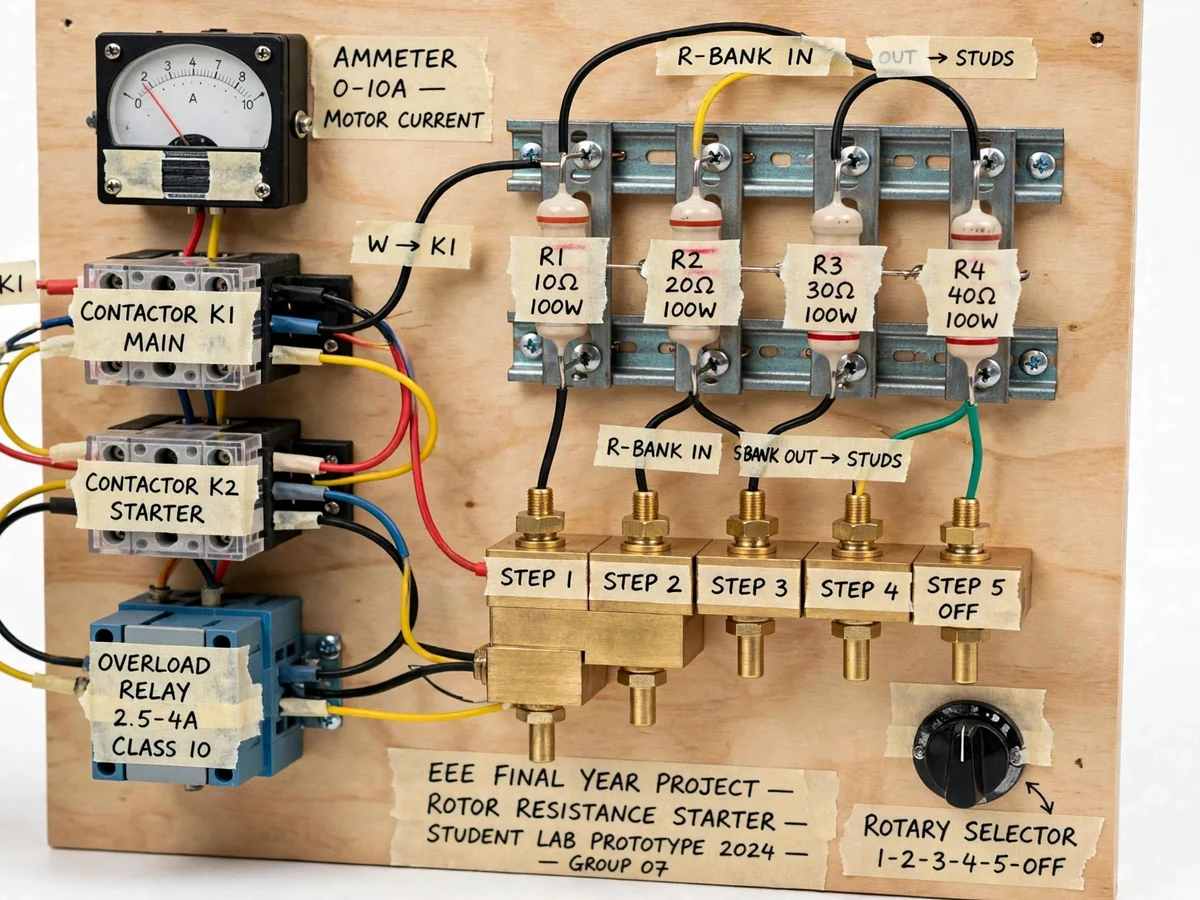
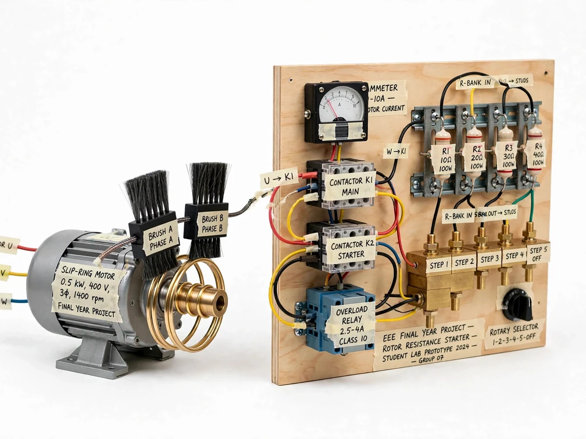
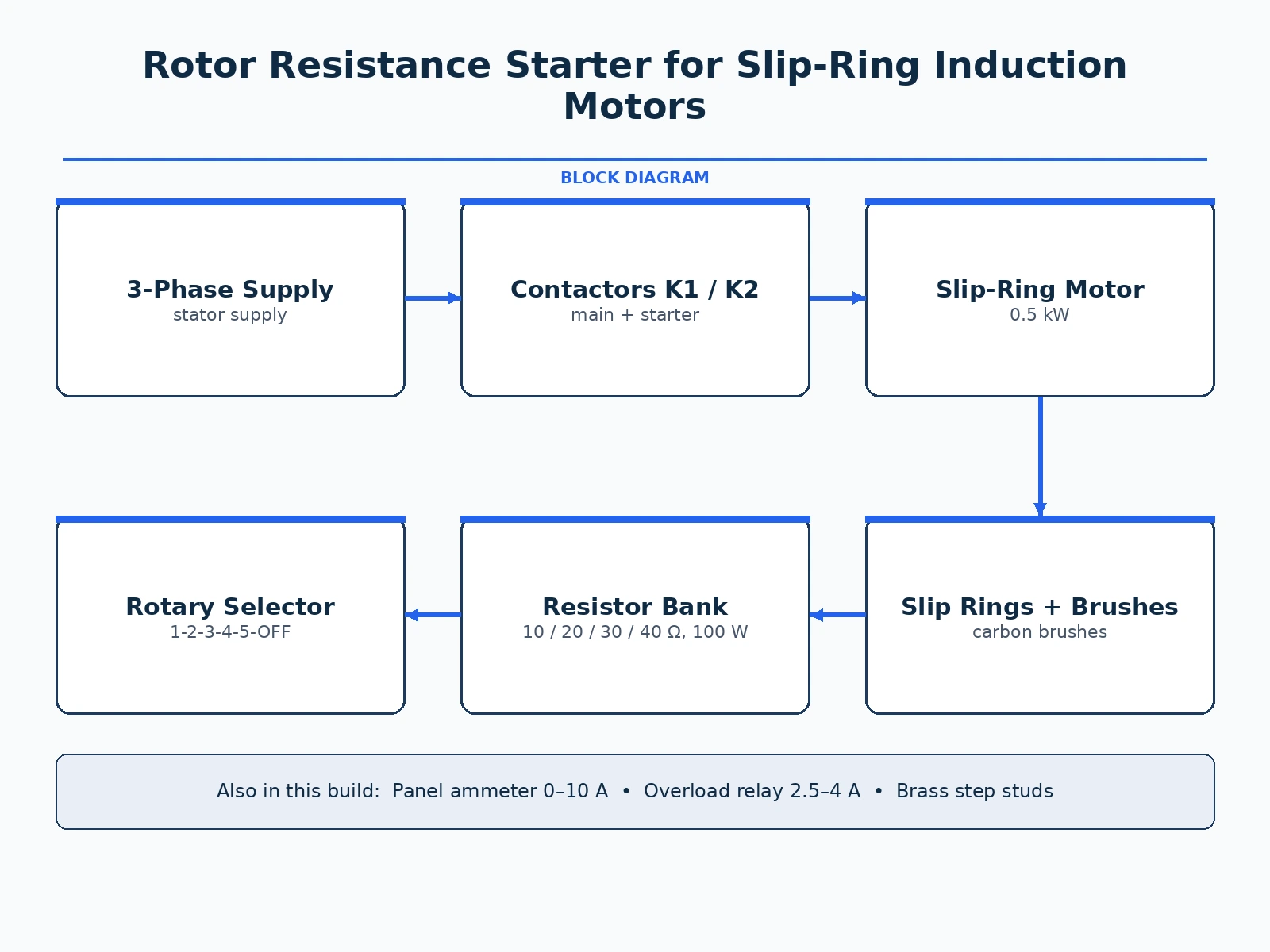
Slip-ring induction motors are chosen where the load needs high starting torque — crushers, conveyors, hoists — and the rotor resistance starter is how they are started: resistance in the rotor circuit shifts the torque curve so maximum torque appears at standstill, then the resistance is cut out in steps as the motor runs up to speed. This project builds the complete starter as a bench panel: a wire-wound resistor bank with brass stud terminals, a rotary selector switch that shorts out one step at a time, main and starter contactors, an ammeter showing the stator current at each step, and a small slip-ring motor with visible slip rings and carbon brushes. The student demonstrates every step of the starting sequence and plots current against step — the torque-slip characteristic made tangible. The report derives the resistance-step calculation from the slip at maximum torque.
Closes the main contactor, then moves the rotary selector through steps 1 to 5 as the motor accelerates.
Follow the working sequence
How it works
- With the selector at step 1, full external resistance is in the rotor circuit; the main contactor K1 is closed.
- The motor starts with high rotor resistance — maximum torque near standstill and limited stator current, visible on the ammeter.
- As the motor accelerates, the operator moves the selector to step 2, shorting out the first resistance section.
- Steps 3 and 4 cut out further resistance as speed rises, each transition visible as a current step on the ammeter.
- At the final position the rotor is short-circuited (slip rings shorted) and the motor runs as a normal induction motor.
- The overload relay rides through the starting sequence and protects against sustained overload in running.
Tech stack:
- Slip-ring induction motor, 0.5 kW
- Wire-wound resistor bank (stepped)
- Brass stud terminals
- Rotary selector switch 1-2-3-4-5-OFF
- Contactors K1 (main) and K2 (starter)
- 0–10 A panel ammeter
- Overload relay 2.5–4 A, Class 10
- Carbon brushes and slip-ring assembly
| Parameter | Value |
|---|---|
| Motor | 0.5 kW, 400 V, 3-phase, 1400 rpm slip-ring (nameplate value) |
| Resistor steps | 10 Ω / 20 Ω / 30 Ω / 40 Ω, 100 W wire-wound (nameplate values) |
| Selector | Rotary, positions 1-2-3-4-5-OFF (design value) |
| Ammeter | 0–10 A panel meter (nameplate value) |
| Overload relay | 2.5–4 A, Class 10 (nameplate value) |
| Contactors | K1 main, K2 starter (datasheet values per selected units) |
| Starting current | Limited to approximately 2–3× rated across steps (expected) |
| Panel | Bench demonstration panel (expected) |
Project features
- [Stepped resistor bank] Wire-wound power resistors (10 Ω, 20 Ω, 30 Ω, 40 Ω, 100 W) provide the external rotor resistance in discrete steps.
- [Brass step studs] Brass stud terminals give positive, low-resistance tap points for each starting step.
- [Rotary selector switch] A 1-2-3-4-5-OFF rotary selector shorts out resistance steps in sequence as the motor accelerates.
- [Main and starter contactors] K1 (main) and K2 (starter) contactors switch stator supply and starter logic with proper sequencing.
- [Slip-ring motor with brushes] A 0.5 kW slip-ring motor with visible brass slip rings and carbon brush holders (phase A/B) shows where the resistance connects.
- [Panel ammeter] A 0–10 A ammeter displays stator current at each step, so the current-limiting effect is directly readable.
- [Overload relay] A 2.5–4 A Class 10 overload relay protects the motor during the starting sequence and running.
What is included
- Fully wired rotor resistance starter panel with slip-ring motor
- Stepped resistor bank with brass stud terminals
- Wiring diagram and step-sequence chart
- Starting-sequence demonstration procedure
- Project report PDF (background, slip-torque theory, resistance-step calculation, test procedure)
- PPT presentation for final review
- Viva Q&A preparation document (slip-ring vs squirrel-cage, torque-slip curves, starting methods)
Limitations & prerequisites
- Resistor values are selected for the demonstration motor; a different motor needs the step calculation redone (the method is in the report).
- Stepping is manual via the rotary selector — automatic timed stepping is listed as future scope.
- Resistors dissipate heat during starting; the procedure defines the duty cycle and cooling pauses.
- Starting current figures are expected values for the demo motor, not guaranteed across supplies.
- Brushes and slip rings need periodic inspection and cleaning; the maintenance section covers this.
- The panel is a laboratory demonstrator, not an industrial starter cubicle.
Frequently Asked Questions
Why add resistance to the rotor to start the motor?
Rotor resistance shifts the torque-slip curve so peak torque occurs at standstill (slip = 1), giving high starting torque; it also limits rotor — and therefore stator — current.
Why cut the resistance out in steps?
As the motor speeds up, keeping full resistance would waste power and limit speed; each step re-optimises the torque curve for the new slip until the rotor is shorted for normal running.
How is this different from a star-delta or soft starter?
Those reduce stator voltage on squirrel-cage motors (sacrificing starting torque); the rotor resistance starter keeps full stator voltage and gets high torque — the reason slip-ring motors exist for heavy starts.
What do the slip rings and brushes do?
They bring the rotating rotor winding out to the stationary resistor bank — the brushes ride on the brass rings and carry rotor current to the external steps.
How are the step values chosen?
From the slip at maximum torque: the report works the standard calculation that sizes each step so current stays within limits across the start.
Is this project suitable for a final-year project?
Yes — for Electrical Engineering. It is one of the richest machines-lab topics: torque-slip theory, real calculations and a step-by-step live demonstration. Suitable for B.E./B.Tech final-year projects in Electrical Engineering.
Components & software requirements
- Slip-ring induction motor, 0.5 kW
- Wire-wound resistor bank (stepped)
- Brass stud terminals
- Rotary selector switch 1-2-3-4-5-OFF
- Contactors K1 (main) and K2 (starter)
- 0–10 A panel ammeter
- Overload relay 2.5–4 A, Class 10
- Carbon brushes and slip-ring assembly
Delivery information
Built-to-order project. Delivery timeline is shared after order confirmation based on current queue.
Support terms
Complete documentation, setup guide, and viva preparation included. Support for setup and explanation provided.
Download free synopsis (PDF)
Enter your name and WhatsApp number — the synopsis PDF downloads immediately. We may send occasional project updates on WhatsApp; no spam.