
More project photos (3)
The problem
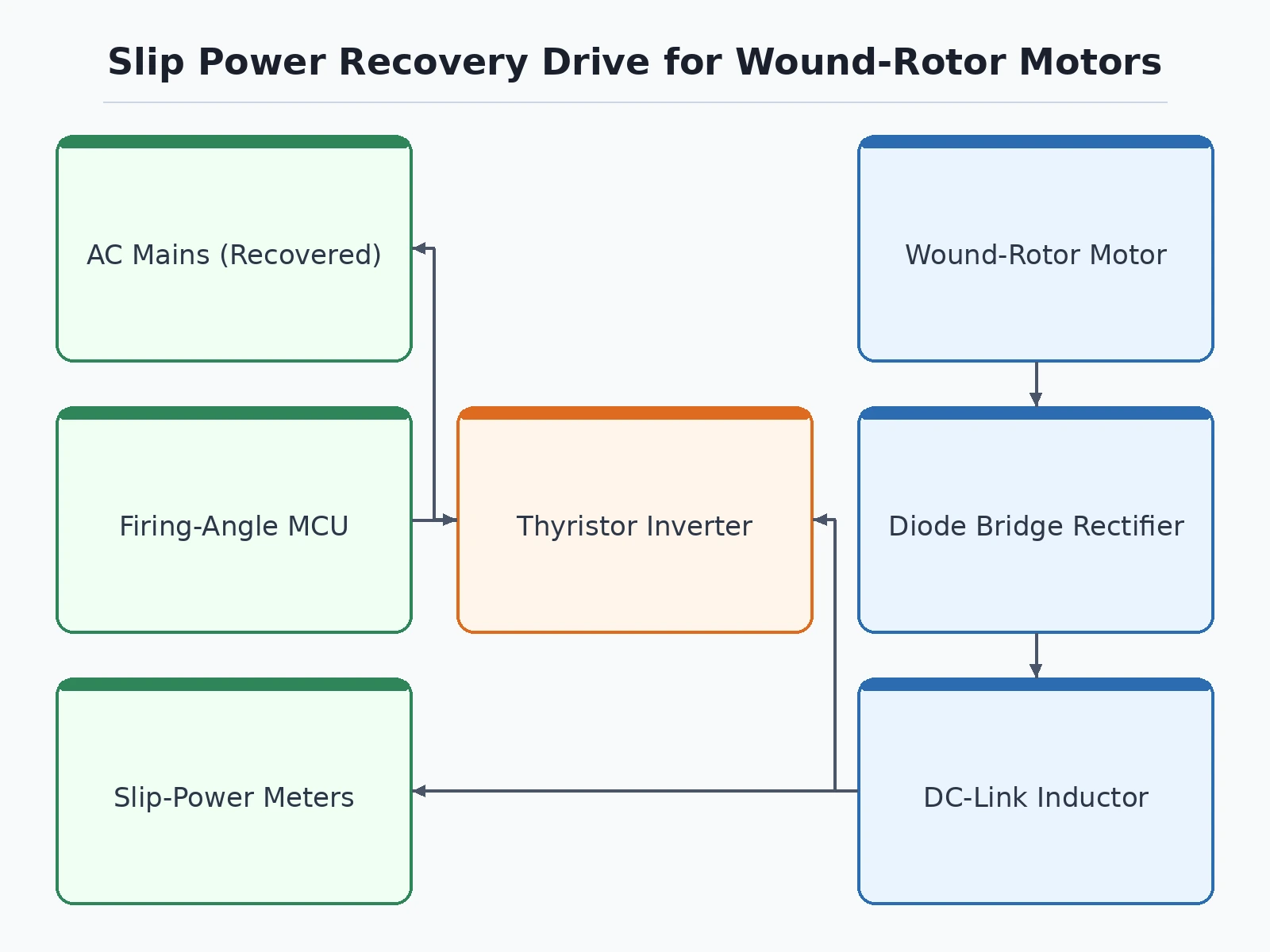
Speed control of a wound-rotor induction motor below synchronous speed is classically done by inserting resistance in the rotor circuit — simple, but every watt of slip power is burned as heat in the resistors. The static Scherbius scheme fixes exactly this waste: the slip-frequency power from the rotor slip rings is rectified and fed back into the AC supply through a line-commutated inverter, so the energy that resistance control would destroy is recovered instead. This project builds that scheme at laboratory scale: a fractional-HP wound-rotor motor, a three-phase diode bridge on the rotor side, a DC-link inductor, and a thyristor bridge operated in inverter mode returning power to the mains. A firing-angle controller sets the inverter angle, giving smooth subsynchronous speed control — and a switchable rotor-resistor bank lets students measure the before/after difference the recovery makes.
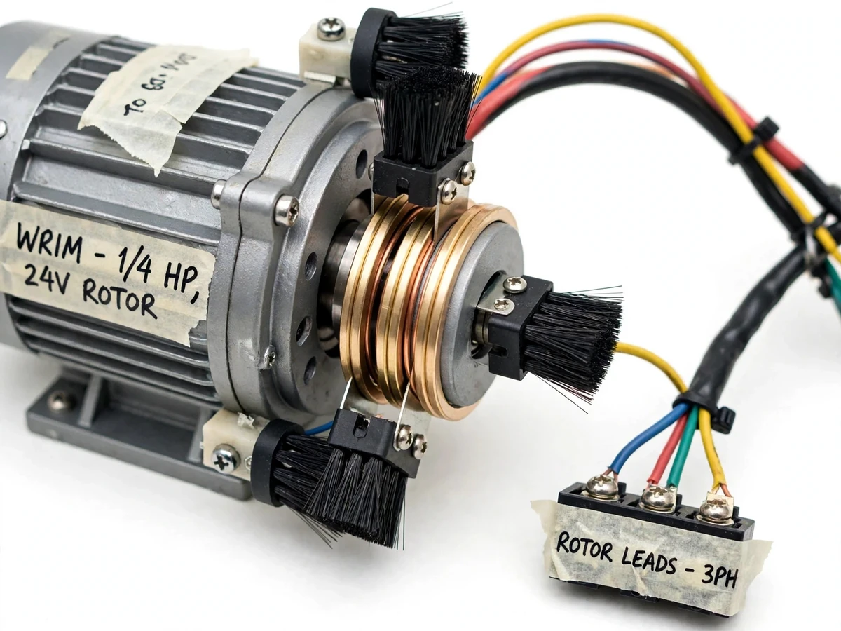
Wound-rotor motor whose slip rings expose rotor power.
Follow the working sequence
How it works
- The wound-rotor motor runs from the AC mains; its rotor slip rings carry slip-frequency AC proportional to the slip.
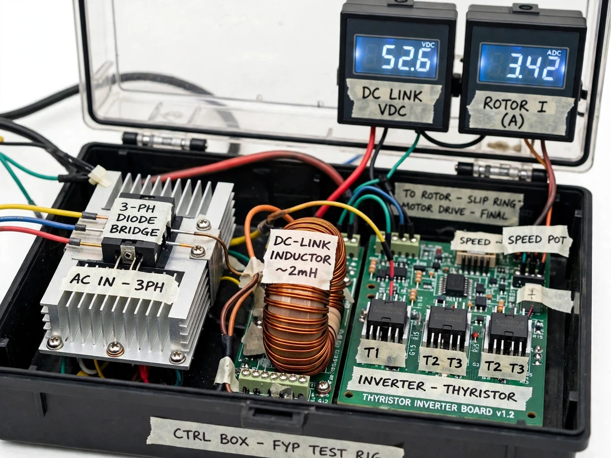
- A three-phase diode bridge rectifies the rotor output; a DC-link inductor smooths the resulting DC.
- A thyristor bridge, synchronized to the mains and fired in inverter mode, converts the DC-link power back to AC and feeds it into the supply.
- The firing-angle controller sets the inverter angle: advancing it raises the counter-EMF, increases the effective rotor resistance electrically and slows the motor — speed control without physical resistors.
- Flipping the mode switch inserts the rotor-resistor bank instead, demonstrating conventional dissipative control for comparison.
- Meters on the DC link and the mains side let students observe the slip power being recovered rather than burned.
Tech stack:
- Fractional-HP wound-rotor (slip-ring) induction motor
- Three-phase diode bridge rectifier (rotor side)
- Line-commutated thyristor inverter bridge (mains side)
- DC-link smoothing inductor
- Microcontroller firing-angle controller with mains synchronization
- Panel meters (DC-link V/I, mains-side indication)
| Parameter | Value |
|---|---|
| Motor | Fractional-HP wound-rotor induction motor with slip rings |
| Rectifier | Three-phase diode bridge on the rotor slip power |
| Inverter | Line-commutated thyristor bridge returning power to the mains |
| Speed range | Below synchronous speed; design target approx. 50–100% of synchronous speed |
| Control | Inverter firing-angle controller with commutation-margin limit |
| Metering | DC-link voltage/current, mains-side power indication |
| Comparison | Switchable rotor-resistor bank for resistance-control mode |
| Protection | Line fuses, DC-link inductor, firing-angle limits |
Project features
- [Wound-rotor motor with slip-ring access] A fractional-HP slip-ring induction motor exposes the rotor circuit so slip power can be tapped, rectified and recovered.
- [Rotor diode-bridge rectifier] A three-phase diode bridge converts the slip-frequency rotor output to DC for the link inductor.
- [Line-commutated inverter] A thyristor bridge operated in inverter mode returns the DC-link power to the AC mains — the heart of the Scherbius recovery.
- [Firing-angle speed control] Varying the inverter firing angle changes the counter-EMF seen by the rotor circuit, giving smooth speed control below synchronous speed.
- [Comparison mode] A switchable rotor-resistor bank lets the same motor run with plain resistance control, so students can compare wasted versus recovered slip energy on the meters.
- [Slip-power metering] DC-link voltage and current meters plus mains-side indication show where the slip energy goes in each mode.
- [Protection built in] Line fuses, a DC-link smoothing inductor and a commutation-margin limit on the inverter firing angle protect the bridges.
What is included
- Working slip-power recovery drive panel with wound-rotor motor rig
- Controller firmware source (firing-angle control, synchronization)
- Circuit and wiring documentation, component list
- Operating procedure: recovery mode vs resistance-control comparison
- Project report PDF (Scherbius theory, power-flow analysis, comparison procedure)
- PPT presentation for final review
- Viva Q&A preparation document (slip power, Scherbius vs Kramer, inverter commutation)
- Setup and safety guide
Advantages
- Recovers slip energy instead of wasting it as heat in rotor resistors, by rectifying the rotor output and returning it to the AC mains through the line-commutated inverter.
- Smooth subsynchronous speed control by varying the inverter firing angle, which changes the counter-EMF seen by the rotor circuit.
- Built-in comparison mode: the switchable rotor-resistor bank lets the same motor run with plain resistance control, so recovered versus wasted slip energy can be compared on the meters.
- Slip-power metering is built in, with DC-link voltage and current meters plus mains-side indication showing where the slip energy goes in each mode.
- Protection is part of the build: line fuses, a DC-link smoothing inductor and a commutation-margin limit on the inverter firing angle protect the bridges.
Disadvantages
- Speed control is subsynchronous only; it cannot run the motor above synchronous speed, which would need a doubly-fed arrangement outside this project's scope.
- The line-commutated inverter draws reactive power and harmonic currents from the mains, so the panel suits short laboratory demonstrations rather than continuous connection without filtering.
- At laboratory scale the recovered power is small; the value of the build is demonstrating the principle and the measurement procedure, not the wattage.
- Wound-rotor motors are less common in the current market, so sourcing a suitable fractional-HP unit is part of the build timeline.
- Efficiency and recovery figures are measured by the student during their own comparison tests; no performance numbers are pre-claimed.
Limitations & prerequisites
- Speed control is subsynchronous only — this scheme cannot run the motor above synchronous speed; that needs a doubly-fed arrangement, outside this project's scope.
- The line-commutated inverter draws reactive power and harmonic currents from the mains; the panel is for short laboratory demonstrations, not continuous connection without filtering.
- At laboratory scale the recovered power is small — the value of the build is demonstrating the principle and the measurement procedure, not the wattage.
- Wound-rotor motors are less common in the current market; sourcing a suitable fractional-HP unit is part of the build timeline.
- Efficiency and recovery figures are measured by the student during their own comparison tests — no performance numbers are pre-claimed.
Frequently Asked Questions
How is this different from rotor-resistance speed control?
Resistance control burns slip power as heat in the rotor resistors. This drive rectifies the slip power and inverts it back into the mains — the same speed control, but the energy is recovered instead of wasted.
Which controller is used?
A microcontroller synchronized to the mains generates the thyristor firing pulses for the inverter bridge, with the firing angle adjustable to set speed.
Can the motor run above synchronous speed?
No — the static Scherbius scheme gives subsynchronous control only. Super-synchronous operation needs a doubly-fed (rotor-side converter) arrangement.
What are the main limitations?
Subsynchronous range only; inverter harmonics limit it to short lab demos; recovered power is small at this scale; efficiency numbers come from the student's own measurements.
What power supply is needed?
A standard 230 V AC lab outlet for the motor and the inverter side; the rotor-side circuitry is derived from the slip rings.
Is this project suitable for a final-year project?
Yes — for Electrical Engineering programs. It demonstrates electrical machines, power electronics, energy recovery and honest experimental comparison in one build. Suitable for B.E./B.Tech final-year projects in Electrical Engineering.
Components & software requirements
- Fractional-HP wound-rotor (slip-ring) induction motor
- Three-phase diode bridge rectifier (rotor side)
- Line-commutated thyristor inverter bridge (mains side)
- DC-link smoothing inductor
- Microcontroller firing-angle controller with mains synchronization
- Panel meters (DC-link V/I, mains-side indication)
Delivery information
Built-to-order project. Delivery timeline is shared after order confirmation based on current queue.
Support terms
Complete documentation, setup guide, and viva preparation included. Support for setup and explanation provided.
Download free synopsis (PDF)
Enter your name and WhatsApp number — the synopsis PDF downloads immediately. We may send occasional project updates on WhatsApp; no spam.
Kumar et al. - Review of Slip Power Recovery Scheme (IJRRA, 2015)