
More project photos (2)
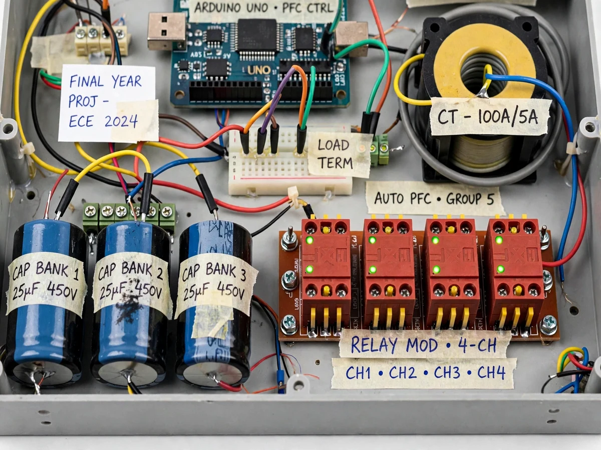

The problem
Inductive loads — motors, tube-light chokes, transformers — draw reactive power that does no useful work but still flows through cables and switchgear. Utilities size infrastructure for total current, so they bill industrial consumers for apparent power (kVA), not just real power (kW): a low power factor means paying for capacity never converted into work, through demand charges and penalties. The fix is understood — capacitors supply the reactive power locally — but a fixed bank cannot track a varying load. Too little capacitance leaves the penalty in place; too much pushes the power factor leading, causing overvoltage. Factories use automatic correction panels that measure phase lag and switch capacitor stages in and out to hold power factor near a target. That control loop — sensing voltage and current, extracting the phase angle, switching stages without hunting or overcorrection — is what a small microcontroller can demonstrate at bench scale.
How it works
- A potential transformer steps the mains voltage down for sensing, and a current transformer samples the load current.
- Two zero-crossing detector circuits (op-amp comparators) convert both waveforms into square waves.
- The Arduino measures the time delay Δt between the voltage and current zero crossings and computes the phase angle φ = 2πf·Δt, then power factor = cos φ.
- If the load is lagging below the target power factor (typically 0.95), the firmware switches in capacitor stages one by one until the power factor is corrected.
- When the load drops or is switched off, stages are switched out in reverse — with discharge delays — so the system never overcorrects into a leading power factor. The LCD shows the whole process live.
Project features
- True phase-angle measurement with dual zero-crossing detector circuits
- Power factor computation (cos φ) with live display
- Automatic 4-stage capacitor bank switching via relay modules
- Live LCD readout: power factor, kW, kVAR and active capacitor stages
- Auto/manual operating modes for demonstration flexibility
- Leading/lagging indication — avoids overcorrection into leading power factor
- Capacitor discharge resistors for safety between switching operations
- Demo inductive load (choke/ballast) to show before/after correction
- Fuse protection on the capacitor bank and control circuitry
- Scaled single-phase demo of a three-phase industrial concept
What is included
- Assembled APFC panel with capacitor bank
- Complete source code (Arduino IDE, well-commented)
- Circuit diagram and wiring schematic
- Project report PDF (synopsis, design, calculations, results, conclusion)
- PPT presentation for final review
- Viva Q&A preparation document
- Calibration and demo procedure guide
FAQs
- Why does a low power factor cost money? Utilities bill industrial consumers on kVA demand — a lagging power factor means more current (and bigger cables, transformers and losses) for the same useful kW. Correcting toward unity cuts demand charges and I²R losses, which is why factories install APFC panels.
- How does the zero-crossing detector measure phase difference? Each ZCD (an op-amp comparator) turns its sine wave into a square wave whose edge marks the zero crossing. The Arduino timestamps the voltage edge and the current edge; the delay Δt gives the phase angle φ = 2πf·Δt, and power factor = cos φ.
- Why use multiple capacitor stages instead of one big capacitor? A single fixed capacitor would overcorrect a light load into leading power factor — causing overvoltage and its own penalties. Staged switching adds only as much kVAR as the load needs, and sheds stages as the load drops.
- Is working with 230 V mains safe for a student demo? The panel is built enclosed, with fuses, isolated PT/CT sensing and discharge resistors across every capacitor. Treat it as mains equipment — no open-panel probing during powered demos.
- Can it be demoed with a real motor? Yes — a small single-phase induction motor is an ideal inductive load and shows a clear before/after power-factor improvement. The report includes a sample test-table format for recording load, uncorrected and corrected power factor.
- How is this different from a manual capacitor bank? Manual banks cannot track a varying load and risk overcorrection. The APFC loop — sense, compute, switch, re-measure — is a closed-loop control system, which adds control-systems review material on top of the power-systems content.
Limitations & prerequisites
- Single-phase scaled demo of what is usually a three-phase industrial panel — the correction principle is identical, but stage kVAR ratings are demo-scale.
- Intended for linear inductive loads; heavily harmonic (non-linear) loads need detuned reactors, which are outside this build's scope.
- Capacitors need a short discharge interval between switching operations — rapid hunting is prevented in firmware by design.
- Power-factor accuracy is demonstrative; it will not match a calibrated utility energy meter.
Components & software requirements
- Arduino Nano/Uno microcontroller
- 2x zero-crossing detector circuits (LM358 op-amps)
- Potential transformer (mains to low-voltage sensing)
- Current transformer (load-current sensing)
- 4-channel relay module (capacitor switching)
- 4-stage capacitor bank with discharge resistors
- 16x2 LCD (live PF, kW, kVAR readout)
- Demo inductive load (tube-light choke)
Specifications
| Parameter | Value |
|---|---|
| Microcontroller | Arduino (ATmega328P, 16 MHz) |
| Phase measurement | Dual ZCD, timer-based Δt capture |
| PF display range | 0.00–1.00, with leading/lagging indication |
| Capacitor stages | 4 automatic stages + manual mode |
| Capacitor rating | X2/motor-run capacitors with discharge resistors |
| Relay rating | 10 A / 250 V AC per channel |
| Display | 16×2 LCD — PF, kW, kVAR, stage status |
| Sensing | PT (voltage) + CT (current), isolated from mains |
| Target PF | Configurable, default 0.95 lagging |
| Protection | Fuses on capacitor bank and control supply |