
More project photos (2)
The problem
Level crossings are among the deadliest points on any railway network. Where roads meet tracks, safety depends on a gate closed in time, every time — yet many crossings still depend on a gateman's judgment or, at unmanned crossings, nothing at all. The failure modes are familiar: a gate opened too early, a train from the unexpected direction, a warning missed in traffic noise. Automating the crossing removes human timing error: sensors detect the approaching train on either side, the barrier closes with lights and sound, and reopens only when the train has fully cleared. Real railways use track circuits and axle counters; at model scale the same logic — direction-aware detection, a strict state machine and fail-safe defaults — can be built with an Arduino, IR sensor pairs and a servo barrier. This project is that working model, including the safety reasoning behind it.
How it works
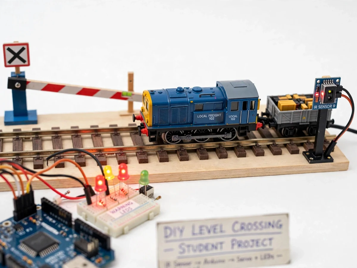
- Two IR sensor pairs are mounted at set distances on either side of the crossing; each pair is a transmitter beaming across the track to a receiver.
- When a train breaks the beam of the approach-side sensor, the Arduino registers TRAIN APPROACHING, starts the flashing LEDs and buzzer, and drives the servo to close the barrier.
- The LCD updates through the sequence: TRAIN APPROACHING → GATE CLOSED → TRAIN PASSING.
- The train passes through the crossing; while either beam is broken the gate stays closed and the alarm keeps sounding.
- Once the train clears the exit-side sensor's beam, the Arduino confirms the crossing is empty, stops the alarm and drives the servo back to open.
- If a sensor beam stays broken abnormally long or a sensor fails, the system falls back to fail-safe: barrier closed, alarm on, LCD showing FAULT.
Project features
Automatic train detection with IR sensor pairs on both approaches — covers trains coming from either direction
Bidirectional logic — the system knows which sensor the train hit first and behaves correctly for both directions
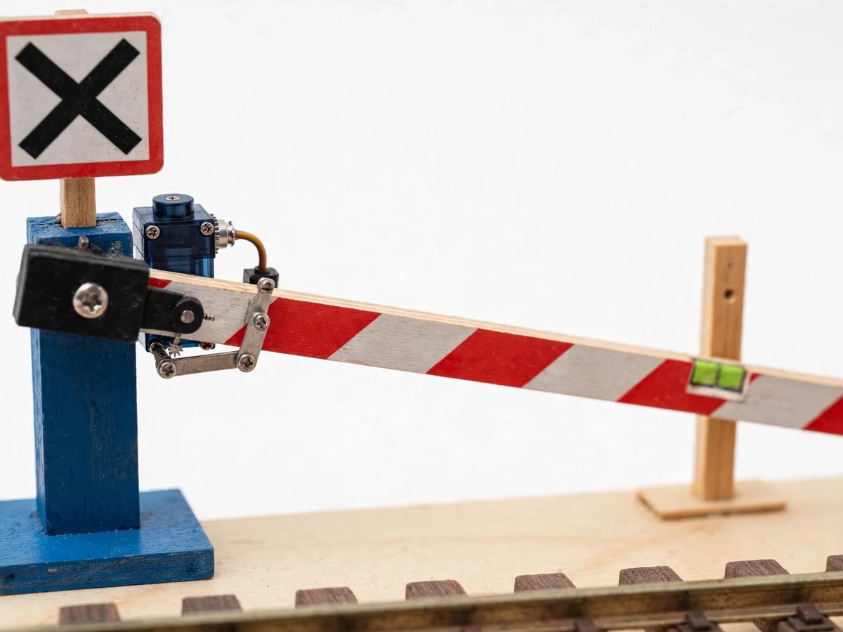
Servo-driven striped barrier arm with smooth close/open motion
Flashing red warning LEDs + loud buzzer alarm while the train approaches and passes
16×2 LCD showing live status: IDLE, TRAIN APPROACHING, GATE CLOSED, TRAIN PASSING
Automatic reopening — the gate opens only after the exit-side sensor confirms the train has fully cleared
Fail-safe behavior — on sensor fault or power loss the barrier stays closed with the alarm sounding
Configurable gate timing (approach distance vs barrier close speed) in firmware
Manual override switch for maintenance mode during demos
Toy train track model included, so the complete sequence runs without external props
What is included
Fully assembled and sequence-tested railway gate model with train track
Complete firmware source code (Arduino IDE, well-commented state machine)
Circuit diagram and wiring schematic
Sensor alignment and timing-calibration procedure sheet
Project report PDF (crossing accident background, design, timing analysis, results, conclusion)
PPT presentation for final review
Viva Q&A preparation document (state machines, IR sensing, servo control, fail-safe design)
Demo runbook — how to run the train-pass sequence in your review
FAQs
- How does the system know the train's direction? The two sensor pairs are hit in sequence — approach-side first for one direction, exit-side first for the other. The firmware's state machine records the order and applies the correct close/open sequence for both directions, so trains from either side are handled.
- What stops the gate from opening while the train is still passing? The gate reopens only when the exit-side beam goes unbroken AND a clearance timeout elapses — while any beam is broken, the state machine stays locked in CLOSED/PASSING. You can demo this by holding your hand in the beam.
- What happens if a sensor fails? The design is fail-safe: on sensor fault or power loss the barrier stays closed and the alarm sounds. The core safety decision is that a false alarm with a closed gate is always preferable to an open gate with a missed train.
- Why IR sensors and not something else? IR pairs are cheap, direction-sensitive and easy to demo at model scale. The report compares them with real-world alternatives — axle counters, track circuits and ultrasonic sensors — and explains why each suits different scales.
- Can I demo this reliably in my review? Yes — the model ships with the toy train and track, pre-aligned and sequence-tested. The demo runbook walks you through the run: start the train, watch the alarm-barrier-pass-reopen sequence, and show the LCD states.
- How can I extend this project? Common extensions include: RFID train identification, GSM alert to the nearest station, obstacle detection on the track with auto-stop, and a second barrier for the opposite lane.
Limitations & prerequisites
Model scale — IR beam ranges and timings are calibrated for the included track model; a real crossing would use axle counters or track circuits, which the report compares honestly.
IR sensors can false-trigger in direct bright sunlight or with reflective obstacles; the demo is tuned for indoor review-hall lighting.
The barrier is a light model arm — it demonstrates the mechanism, not the torque of a real gate motor.
Fail-safe covers sensor fault and power loss; it does not cover deliberate vehicle intrusion under a closed barrier.
Components & software requirements
Arduino Uno (ATmega328P) with servo library control
IR transmitter–receiver sensor pairs ×2 (approach + exit sides, ~15 cm detection range)
SG90/MG996R servo motor driving the striped barrier arm
Red flashing warning LEDs + active buzzer (alarm circuit)
16×2 LCD with I2C backpack (status display)
Firmware: Arduino IDE (state machine — IDLE, APPROACHING, CLOSED, PASSING, FAULT)
Toy train track model with train (demo hardware)
5 V regulated power with common ground for servo and logic
| Parameter | Value |
|---|---|
| Controller | Arduino Uno (ATmega328P, 16 MHz) |
| Train detection | IR transmitter–receiver pairs ×2, both approaches |
| Detection range | ~15 cm beam break per sensor (model scale) |
| Barrier | Servo-driven striped arm, 90° open/close travel |
| Gate close time | ~2 s with smooth servo ramping |
| Alarms | Flashing red LEDs + active buzzer during approach and passing |
| Display | 16×2 LCD: IDLE / TRAIN APPROACHING / GATE CLOSED / TRAIN PASSING / FAULT |
| Logic | Direction-aware state machine; reopen only after full clearance |
| Fail-safe | Gate closed + alarm on sensor fault or power loss |
| Demo track | Toy train track with train included |
| Power | 5 V regulated; servo on separate supply rail with common ground |