
More project photos (2)
The problem
Small workshops, laboratories and institutional buildings run large numbers of lightly loaded induction motors, fluorescent/old lighting ballasts and transformers — loads whose current lags the voltage. When the lagging power factor stays low, the same real power draws more current, heating cables and transformers, and utilities penalise it: LT tariff structures bill partly on kVA demand and add surcharges when power factor falls below the sanctioned threshold. A single fixed capacitor corrects only one operating point — at light load it over-corrects and drives the power factor leading, which utilities penalise too. The real engineering answer is a bank of capacitor steps switched in and out automatically as the load changes. This project builds exactly that: a panel that senses power factor in real time and switches AC-rated capacitor steps through contactors to hold it near the target, with the measurement and switching logic visible for study.
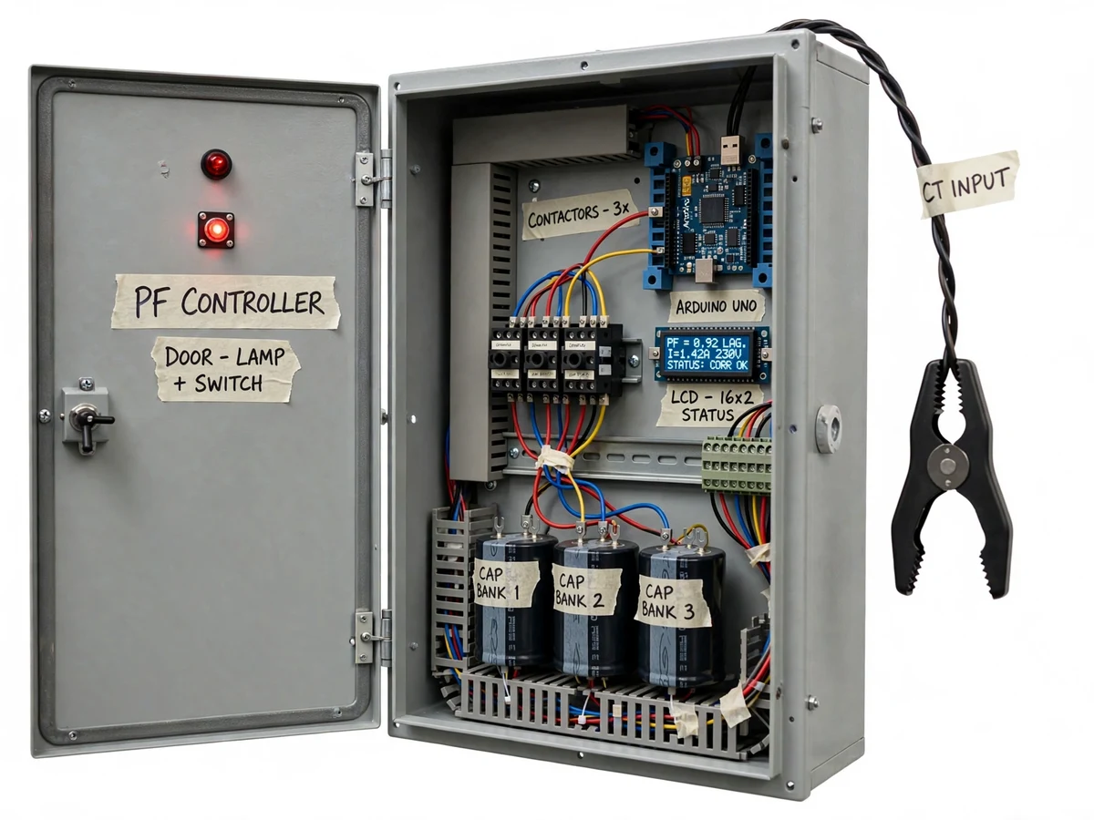
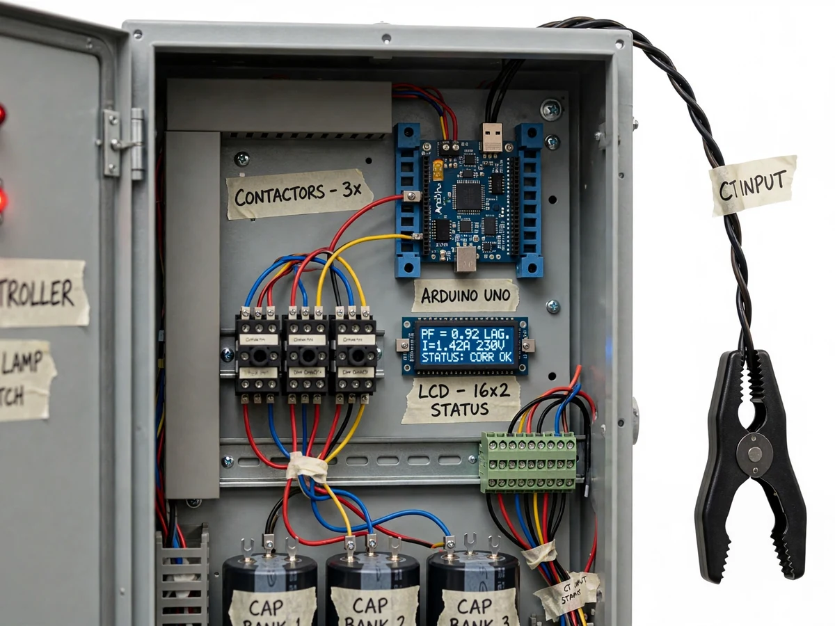
Split-core CT clamped on the load conductor; its burden-resistor output feeds the zero-cross detector for current phase timing.
Follow the working sequence
How it works
- A split-core current transformer clamped on the load conductor and an isolated voltage sensor feed scaled AC waveforms to the Arduino through conditioning and zero-crossing detector stages.
- Firmware timestamps the voltage and current zero crossings of the 50 Hz waveform; the time difference converts directly to phase angle, and power factor is cos φ with lag/lead direction.
- From measured power factor and load current, the controller estimates the reactive (kVAr) deficit against the configured target of 0.95 lagging.
- It selects the combination of the three capacitor steps whose total kVAr most closely covers the deficit without driving the power factor leading.
- Contactor drivers switch the selected steps in one at a time with a safe delay between steps, while the LCD updates PF, V, I and active steps.
- Every measurement cycle re-senses and adjusts; a deadband around the target stops rapid step hunting on fluctuating loads.
- In manual mode, panel push-buttons switch each step directly so the student can demonstrate uncorrected, partially corrected and corrected states during the viva.
Tech stack:
- Arduino Uno (ATmega328P), Arduino IDE (Embedded C)
- 440 V AC-rated power capacitors, 3 steps
- AC contactors with relay driver stage
- Split-core current transformer with burden resistor
- ZMPT101B isolated voltage sensor module
- Opto-isolated zero-crossing detectors
- 16x2 character LCD (I2C interface)
- MS-steel enclosure, MCB incomer, terminal blocks
| Parameter | Value |
|---|---|
| Supply | 230 V AC, 50 Hz, single-phase (design) |
| Maximum demo load | Up to approximately 2 kW / 9 A resistive-inductive test load (design target) |
| Correction target | PF ≥ 0.95 lagging (design target, not a measured claim) |
| Capacitor bank | 3 steps of AC-rated 440 V power capacitors (design values) |
| Current sensing | Split-core CT with burden resistor, shorting provision (typical) |
| Measurement method | Zero-crossing timing on 50 Hz waveform (expected) |
| Step re-switch delay | ≥ 10 s between reconnections (design, for capacitor discharge) |
| Display | 16x2 LCD: power factor, voltage, current, active steps |
| Protection | MCB incomer, discharge resistors across steps, burdened CT secondary (design) |
| Enclosure | MS-steel panel, approximately 450 × 350 × 200 mm (design) |
Project features
- [Zero-crossing power-factor sensing] Detects the timing between voltage and current zero crossings on the 50 Hz waveform to compute power factor and lag/lead direction, using a split-core CT for current and an isolated voltage sensor with opto-coupled zero-cross detectors.
- [Three-step switched capacitor bank] Three AC-rated capacitor steps switch in combinations that track the load's reactive demand, so light and heavy loads are corrected without the over-correction a single fixed bank causes.
- [Contactor switching with discharge timing] AC contactors (not bare relay modules) handle the capacitor inrush; firmware enforces a safe re-switch delay so each step discharges fully before reconnecting.
- [Live LCD readout of PF, V and I] A 16x2 LCD shows measured power factor, line voltage, load current and the number of active capacitor steps, refreshed every measurement cycle.
- [Auto and manual modes] Auto mode switches steps on measured power factor; manual mode forces each step from panel push-buttons for demonstration and viva questioning.
- [Configurable target PF and deadband] Target power factor (design target 0.95 lagging) and hysteresis deadband are firmware constants, so the student can study the hunting-vs-stability trade-off of control loops.
- [Status and fault indication] Panel LEDs and a buzzer flag under-correction, over-correction (leading) and CT-signal faults.
What is included
- Working APFC prototype panel (enclosure, capacitor bank, contactors, Arduino, CT, LCD)
- Arduino firmware source (Embedded C) with commented PF computation and step logic
- Wiring diagram and panel layout drawing
- Capacitor sizing calculation sheet (theory matched to the build)
- Buyer-run calibration and test procedure (step verification, CT phasing check)
- Project report PDF (background, theory, design, procedure)
- PPT presentation for final review
- Viva Q&A preparation document (power-factor theory, capacitor sizing, contactor switching)
- Electrical safety checklist for mains-voltage demonstration
Limitations & prerequisites
- Single-phase 230 V demonstration rig with a design-target rating of ~2 kW / ~9 A; it is a laboratory prototype, not a utility billing-grade APFC panel.
- "PF ≥ 0.95 lagging" is a design target — nothing is physically tested before order, so no corrected-PF figure is claimed as measured; the report documents the procedure the buyer runs to verify correction on their own build.
- Capacitor step sizes are sized by theory for the demo load range; real installations need a licensed engineer to size steps and check resonance and harmonic conditions.
- All mains-voltage wiring, CT installation and energisation must be done under qualified supervision; the safety checklist is mandatory reading before first power-on.
- A CT secondary must never be open-circuited while the primary is energised — the build includes a burden resistor and shorting provision, and the procedure verifies it.
- Re-switching a capacitor step too soon is unsafe; firmware enforces a ~10 s discharge delay, and manual mode should still respect it.
- The unit corrects displacement power factor only; it does not address harmonic distortion or neutral-current issues.
Frequently Asked Questions
Why does a poor power factor cost money?
Under LT tariff structures, billing includes a demand component based on kVA: the same real power at a low lagging power factor draws more current and more apparent power, inflating demand charges and attracting power-factor surcharges below the utility's threshold. Correction cuts the reactive current the utility must supply, which is why industries install APFC panels.
How does the Arduino actually measure power factor?
It does not measure power directly. The zero-crossing detectors mark the instants the voltage and current waveforms cross zero; the time gap between them on the 50 Hz cycle converts to a phase angle, and power factor is cos φ. A current-lagging gap means lagging PF, which is what the capacitor steps correct.
Why switch capacitors in steps instead of one big bank?
Load changes through the day. A fixed bank sized for peak load over-corrects at light load and drives the PF leading — penalised the same way as lagging. Steps let the controller add only the kVAr the load currently needs, tracking demand instead of guessing it.
Why contactors rather than ordinary relay modules?
AC capacitors draw a large inrush when switched. Panel-grade contactors are rated for capacitor-switching duty; small relay modules are not, and their contacts weld or burn. The project uses contactors deliberately to show correct industrial practice, with driver relays between the Arduino and the contactor coils.
Is it safe to demonstrate in college?
The low-voltage control logic can be tested without mains, and the mains stage must be wired and energised only under qualified supervision. The kit ships an electrical safety checklist covering earthing, MCB protection, CT shorting discipline and discharge timing — read it before first power-on.
Is this project suitable for a final-year project?
Yes — for Electrical programs (and E&TC with a power-electronics interest). It spans power-systems theory, measurement and conditioning, embedded control logic and industrial panel practice, giving the student genuine viva depth on every block. Suitable for B.E./B.Tech final-year projects in Electrical and Electronics & Telecommunication.
Components & software requirements
- Arduino Uno (ATmega328P), Arduino IDE (Embedded C)
- 440 V AC-rated power capacitors, 3 steps
- AC contactors with relay driver stage
- Split-core current transformer with burden resistor
- ZMPT101B isolated voltage sensor module
- Opto-isolated zero-crossing detectors
- 16x2 character LCD (I2C interface)
- MS-steel enclosure, MCB incomer, terminal blocks
Delivery information
Built-to-order project. Delivery timeline is shared after order confirmation based on current queue.
Support terms
Complete documentation, setup guide, and viva preparation included. Support for setup and explanation provided.
Download free synopsis (PDF)
Enter your name and email — the synopsis PDF downloads immediately. We may send occasional project updates; no spam, unsubscribe anytime.