
More project photos (2)
The problem
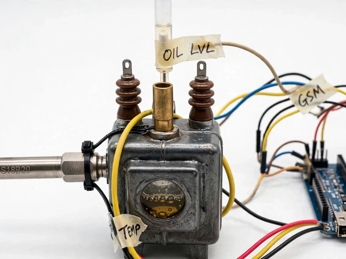
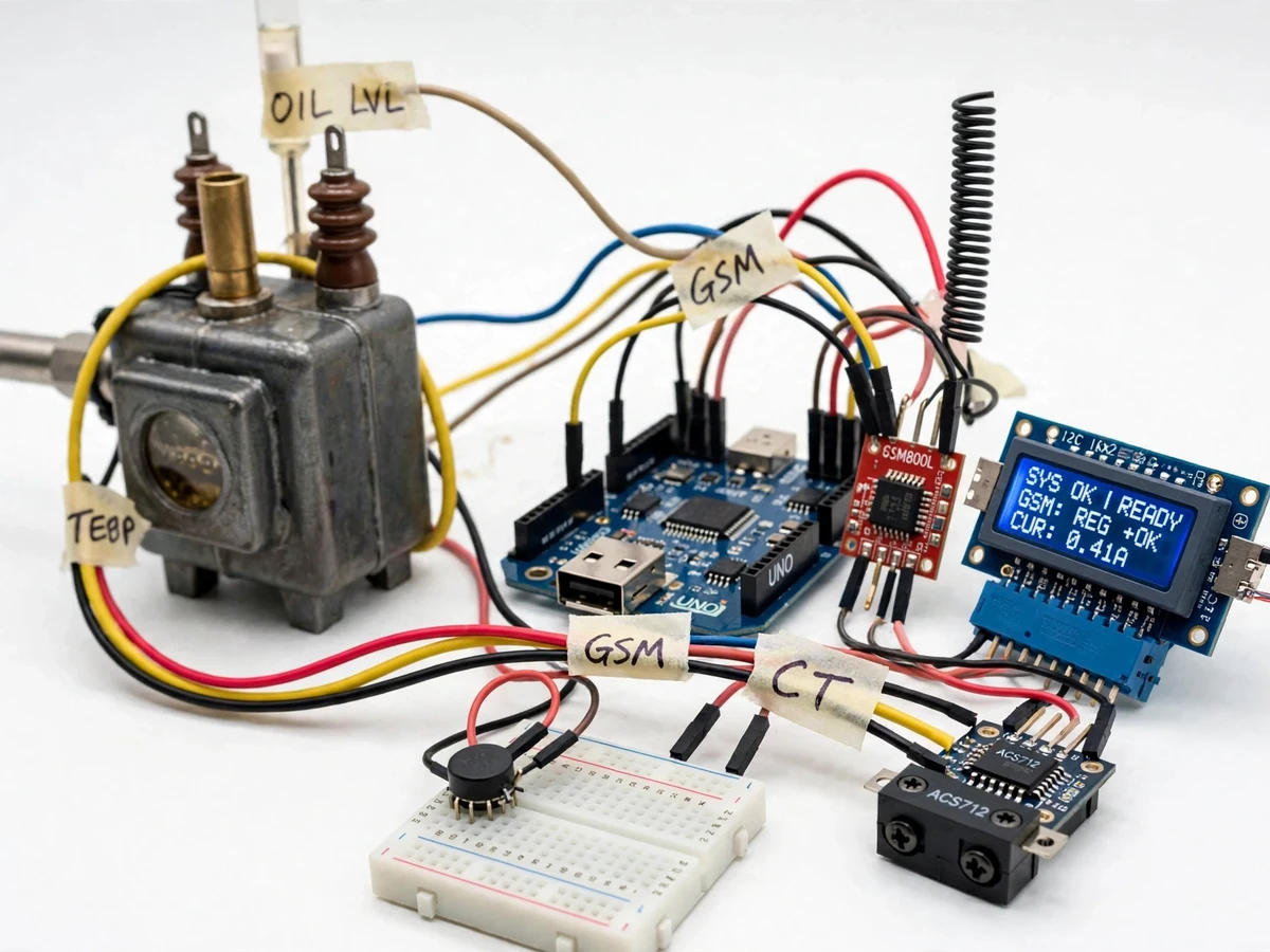
Most distribution transformers in the field are checked only when a patrol team visits, which can be weeks apart. Between visits, three slow-developing faults can quietly escalate: the top-oil temperature climbs under sustained overload, oil level drops through gasket seepage or a failed breather, and the load creeps past the rated current. By the time any of these becomes visible to a patrol, the transformer may already have damaged insulation or tripped a feeder. Continuous condition monitoring is the standard utility-side answer — sensors on temperature, oil level and load, with alarms routed to staff who can act. This project demonstrates that exact loop at model scale: a small demo transformer tank instrumented with a DS18B20 temperature probe, a float-switch level sensor and an ACS712 current sensor, an Arduino reading all three channels, a 16x2 LCD showing live values, and a SIM800L GSM module sending SMS alerts when temperature, level or current cross user-set thresholds. Everything is built on accessible parts with firmware written for explanation, so the student can describe every measurement chain in the viva.
Waterproof DS18B20 probe sampling top-oil temperature about once per second at 12-bit resolution.
Follow the working sequence
How it works
- The DS18B20 probe samples the top-oil temperature about once per second (750 ms conversion at 12-bit, datasheet), the float switch reports oil level as a digital OK/LOW state, and the ACS712 channel is sampled hundreds of times per cycle to compute true RMS load current.
- The Arduino averages the temperature and current readings over a rolling window of a few seconds to reject noise, then refreshes the 16x2 LCD with temperature in °C, level state and current in amperes.
- Each averaged reading is compared against its firmware threshold: high oil temperature, low oil level, and load current above the overload mark.
- On any breach, the controller sounds the buzzer and closes the relay output for a local alarm, and the event is latched so a brief flicker cannot clear it.
- After a debounce delay, the SIM800L sends an SMS naming the fault and its measured value to the configured number; a periodic status SMS is also sent at a configurable interval, and replying "STATUS" returns the live readings on demand.
- The model transformer's secondary is loaded with resistive bulbs to demonstrate overload behavior, and all thresholds can be adjusted in firmware to suit the demonstration.
Tech stack:
- Arduino UNO (ATmega328P)
- Embedded C (Arduino IDE)
- DS18B20 digital temperature sensor (1-Wire)
- ACS712 Hall-effect current sensor module
- SIM800L GSM module (AT commands)
- Float / reed level switch
- 16x2 LCD with I2C backpack
- LM2596 buck converter (GSM supply)
| Parameter | Value |
|---|---|
| Controller | Arduino UNO, ATmega328P at 16 MHz (datasheet) |
| Temperature sensor | DS18B20: −55 to +125 °C range, ±0.5 °C (−10 to +85 °C), 12-bit / 0.0625 °C (datasheet) |
| Temperature sampling | Approximately 1 reading/s (750 ms conversion at 12-bit, datasheet); LCD refresh approximately 2 s (expected) |
| Oil-level sensing | Reed float switch, digital OK/LOW; model level column approximately 25 mm of travel (prototype dimension) |
| Current sensor | ACS712-05B: ±5 A range, 185 mV/A sensitivity, ±1.5% at 25 °C (datasheet) |
| RMS current accuracy | ±5% (design target after buyer-performed calibration; not a measured claim) |
| GSM module | SIM800L, quad-band 850/900/1800/1900 MHz; 3.4–4.4 V supply, ≈2 A peak transmit bursts (datasheet) |
| Temperature-rise reference | IEC 60076 ONAN limits — 60 K top-oil rise, 65 K winding rise — used as design reference for thresholds |
| Local outputs | 16×2 LCD (I2C); buzzer ≈85 dB at 10 cm (design target); relay with 5 A rated contact (datasheet) |
| Power supplies | Arduino: 5 V USB or 7–12 V barrel jack (datasheet); SIM800L: LM2596 buck set to ≈4.0 V, 2 A peak capable (expected) |
Project features
- [Top-oil temperature sensing] A waterproof DS18B20 digital probe is mounted on the model tank and reads temperature over −55 to +125 °C at 12-bit resolution with ±0.5 °C accuracy in the −10 to +85 °C band (datasheet values), giving the controller a trustworthy oil-temperature channel.
- [Oil-level monitoring] A reed float switch fitted in the tank's level column closes or opens at the low-level mark, so the controller detects a drop in oil level and can raise an alert before the windings are exposed.
- [Load current sensing] An ACS712-05B Hall-effect module (±5 A range, 185 mV/A per datasheet) sits in series with the model transformer's secondary, and the firmware computes RMS current from fast ADC sampling for the overload channel.
- [GSM SMS alerts] The SIM800L module sends a text message to a configured phone number whenever temperature, oil level or load current crosses its threshold, and also answers a "STATUS" text with the current readings, so monitoring reaches staff without internet.
- [Live 16x2 LCD readout] An I2C 16x2 LCD continuously shows temperature, oil-level state and load current in amperes, so the rig is fully demonstrable at a bench with no phone needed.
- [Local alarm outputs] A buzzer sounds on any threshold breach and a relay output switches an external lamp or contactor circuit, demonstrating how a protection output would behave in a real installation.
- [Configurable alert thresholds] Temperature, low-level and overload limits are set through named constants at the top of the firmware, so the student can tune them to the model or re-derive them from IEC 60076 rise limits and explain the choice in the viva.
What is included
- Working prototype: sensorized model transformer tank with DS18B20 probe, float level switch, ACS712 module, Arduino, SIM800L with antenna, 16x2 LCD, buzzer and relay
- Complete firmware source code with configurable threshold constants
- Wiring diagram and breadboard layout document
- Component list with datasheet references
- Threshold derivation note (IEC 60076 rise limits as design reference)
- Calibration guide for the current channel (buyer-performed procedure)
- Project report PDF (background, sensor theory, methodology, results)
- PPT presentation for final review
- Viva Q&A preparation document (sensors, GSM AT commands, RMS measurement, protection concepts)
Limitations & prerequisites
- The build is a model-scale demonstration rig, not utility switchyard equipment — it must never be connected to a live 11 kV or 230 V distribution network.
- SMS alerts depend on an active 2G SIM with balance; GSM coverage and the recipient network determine alert latency, typically seconds but not guaranteed.
- The float switch reports OK/LOW only, not a continuous level in millimeters.
- The ±5% RMS accuracy figure is a design target after buyer calibration — the report records the actual measured figure from the calibration procedure.
- The SIM800L must be fed 3.4–4.4 V with ≈2 A peak capability (a dedicated buck); powering it from the Arduino 5 V rail causes resets and is documented as a wiring error, not a supported mode.
- DS18B20 reads oil temperature at its mounting point; thermal gradients mean this is an approximation of true top-oil temperature.
Frequently Asked Questions
Which controller is used and can it be swapped for an ESP32?
The build uses an Arduino UNO because the project is a GSM/SMS-based monitor rather than a Wi-Fi one, and the UNO's 5 V ADC matches the ACS712 output directly. An ESP32 variant is offered as an optional customization, but it needs an external ADC or divider for the 5 V sensor and adds Wi-Fi logging scope to the project.
How do the GSM alerts work and do they cost anything?
The SIM800L holds a standard 2G SIM and sends SMS on threshold breaches, periodic status, and "STATUS" replies. SMS costs follow the SIM's plan (typically a few paise per message on Indian prepaid plans); the firmware keeps messages short and the status interval is configurable to control cost.
Can this be fitted to a real transformer at a substation?
Not as shipped — the model rig operates on a low-voltage bench transformer and the enclosure has no HT insulation or certification. The sensing and alert logic transfers directly, but a real installation needs an HT-rated instrumented design and utility approval, which is listed as future scope.
What power supply does the rig need?
The Arduino runs from a 5 V USB adapter or 7–12 V barrel supply, while the SIM800L gets its own LM2596 buck converter set to about 4.0 V with 2 A peak capability, because the GSM transmit bursts reset the module on weak supplies. The bench load bulbs draw from a separate low-voltage source.
How is the current reading calibrated?
The firmware includes named constants for the ACS712 zero-current offset and sensitivity (185 mV/A nominal). The calibration guide has the student measure a known resistive load, record the raw ADC values, and derive the corrected constants, documenting the actual achieved accuracy in the report.
Is this project suitable for a final-year project?
Yes — for Electrical Engineering (and related instrumentation programs). It demonstrates sensor interfacing, RMS measurement, embedded decision logic, GSM communication with AT commands, and protection-style alarm outputs, all tied to a genuine utility problem the student can explain end to end.
Components & software requirements
- Arduino UNO (ATmega328P)
- Embedded C (Arduino IDE)
- DS18B20 digital temperature sensor (1-Wire)
- ACS712 Hall-effect current sensor module
- SIM800L GSM module (AT commands)
- Float / reed level switch
- 16x2 LCD with I2C backpack
- LM2596 buck converter (GSM supply)
Delivery information
Built-to-order project. Delivery timeline is shared after order confirmation based on current queue.
Support terms
Complete documentation, setup guide, and viva preparation included. Support for setup and explanation provided.
Download free synopsis (PDF)
Enter your name and email — the synopsis PDF downloads immediately. We may send occasional project updates; no spam, unsubscribe anytime.