
More project photos (2)
The problem
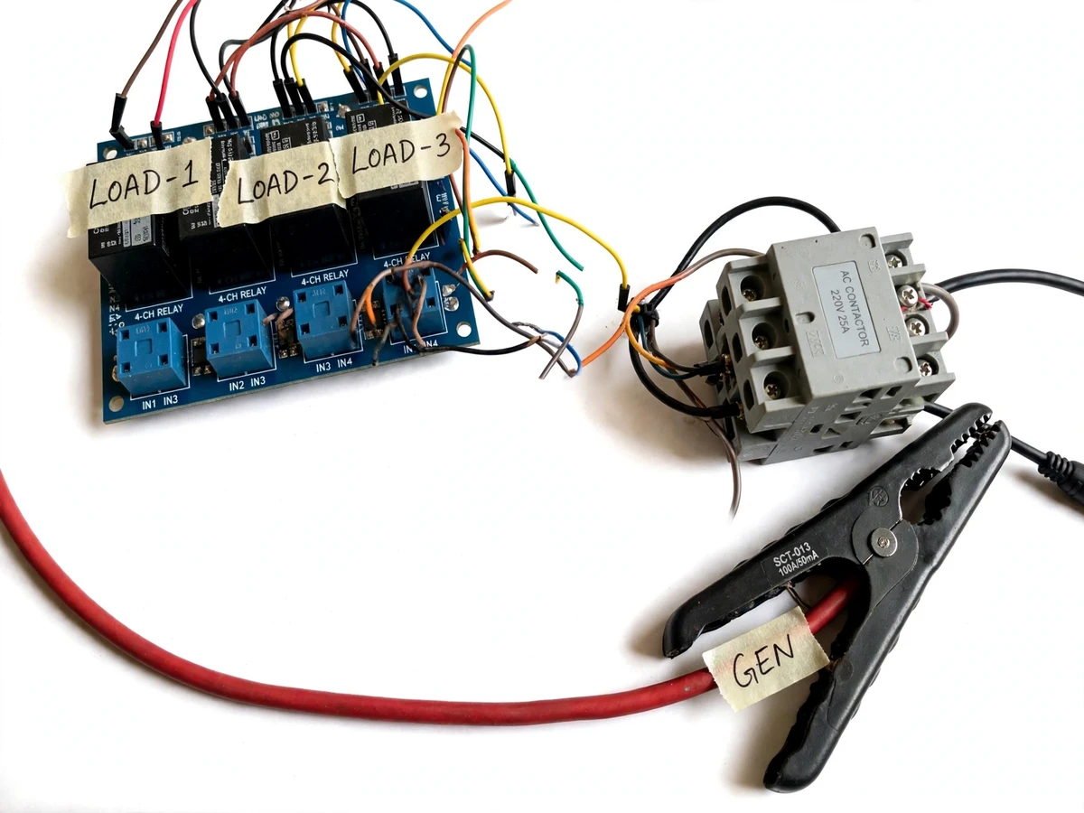
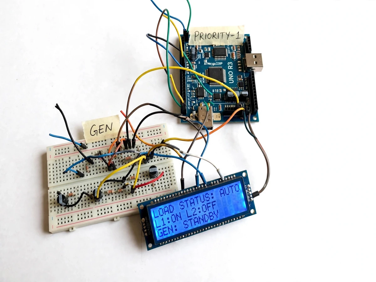
Homes, clinics and small workshops that depend on diesel generators or inverters during power cuts face the same frustration: the moment the mains fail, the limited-kVA backup source gets overloaded by every connected appliance, the generator groans, trips, or burns fuel inefficiently. The standard fix is manual — someone runs around switching things off, and the wrong loads stay on. This project automates that judgement: an Arduino-based controller watches the mains and the generator source, measures the actual load current through an SCT-013 clamp-on current transformer, and sheds non-critical loads in a pre-configured priority order before the source overloads. Four load channels are switched through a relay bank, with heavier loads handled via an external contactor, and a 16x2 LCD continuously reports which loads are on, which were shed, and whether the system is on mains, generator or standby. Because every threshold and priority is configurable, the student demonstrates real electrical-system thinking — source capacity, staged tripping, hysteresis and safe reconnection sequencing — rather than a toy demo.
Relay input giving the controller a binary mains-present signal.
Follow the working sequence
How it works
- A mains-sensing relay input feeds the controller a binary mains-present signal; the SCT-013 current transformer clamps onto the generator/inverter output wire and reports live current to the controller's ADC.
- On mains loss, the controller switches to generator mode, reads the configured per-load priorities and the generator's kVA limit from the configuration table.
- It compares the measured current against staged thresholds: if the total exceeds the configured limit, load channel 4 (lowest priority) is switched off through the relay bank; if the current is still above the limit after the settle delay, channel 3 is shed, and so on up the priority order.
- Each switching action is announced on the 16x2 LCD (for example "L1:ON L2:OFF", "GEN: RUNNING") so the operating state is always visible.
- If current stays above the absolute trip threshold beyond the trip delay, the controller latches a fault state and drops all shed-able loads to protect the source.
- When the mains-sensing input reports the mains have returned, the controller waits the configured reconnect delay, then re-energizes loads one by one in priority order with a pause between each to control inrush.
- The manual override switch at any time hands control to the operator: the automatic logic is paused, loads are switched manually, and the LCD marks the state as manual until the switch is released.
Tech stack:
- Arduino Uno (ATmega328P) controller
- 4-channel 5 V relay module board
- 25 A AC power contactor (heavy loads)
- SCT-013 clamp-on current transformer
- 16x2 character LCD with I2C backpack
- Mains-sensing relay input stage
- Breadboard / general-purpose PCB wiring
- Arduino IDE (embedded C)
| Parameter | Value |
|---|---|
| Controller | Arduino Uno, ATmega328P, 16 MHz (design target) |
| Switched load channels | 4 priority-ordered channels |
| Relay contacts | 10 A, 250 VAC per channel (datasheet value) |
| Heavy-load stage | External 25 A, 220 VAC contactor driven via relay (datasheet value) |
| Current sensing | SCT-013 clamp-on CT, 100 A / 50 mA ratio (datasheet value) |
| Mains sensing | 230 VAC relay input with divider + opto-isolated signal (design target) |
| Display | 16 × 2 character LCD, I2C interface |
| Source modes | Mains, generator/inverter, standby (firmware states) |
| Shed/reconnect delays | Configurable, typical 2–10 s (design target) |
| Trip-on-overload | Configurable threshold + delay, latched fault state |
| Manual override | Hardware selector switch, automatic logic paused |
| Control power | 5 V DC regulated from mains-derived supply (design target) |
Project features
- [Priority-ordered load switching] Four load channels ranked by configurable priority — when demand exceeds the set source capacity, the lowest-priority load is shed first, then the next, until the source stays within its limit.
- [Generator running sensing] An SCT-013 clamp-on current transformer plus a mains-fail relay input detect whether power is coming from the mains or the generator, so shedding rules only apply under backup power.
- [Configurable priority table] Priorities, kVA thresholds, shed/reconnect delays and per-channel enable flags are set through the firmware configuration section — no hardware rewiring needed to change the shedding order.
- [Manual override] A selector switch forces manual mode; each load can then be toggled by hand regardless of the automatic logic, with the LCD flagging manual mode clearly.
- [16x2 status LCD] Shows per-load ON/OFF state, active source (mains/generator/standby) and the current operating mode at a glance.
- [Staged reconnect with delay] When the mains return, loads reconnect one by one with a configurable delay between them, avoiding the inrush spike of everything restarting at once.
- [Trip-on-overload protection] If the measured current stays above the configured limit for the trip delay, all shed-able loads are dropped and the fault state is latched on the LCD until reset.
What is included
- Controller firmware (Arduino/embedded C) with the configurable priority table
- Complete wiring diagram with relay/contactor isolation and earthing notes
- Priority-configuration and threshold-tuning guide
- SCT-013 current-sensor interfacing and calibration procedure (buyer-run)
- Project report PDF (background, source-capacity study, architecture, methodology, results)
- PPT presentation for final review
- Viva Q&A preparation document (load shedding logic, CT sensing, relay vs contactor, hysteresis, inrush)
Limitations & prerequisites
- Each relay channel is rated 10 A at 250 VAC (datasheet) — heavier loads must go through the external 25 A contactor, and contactor wiring for mains must be done or verified by a qualified electrician.
- There is a brief switchover gap when the mains fail; this is a shedding controller, not an uninterruptible power supply — sensitive equipment will see a momentary outage.
- This is prototype-grade load management, not utility-grade protection — it does not replace MCBs, ELCBs, fuses or certified protection devices.
- Current thresholds are set by the buyer's calibration procedure during installation; no measured trip accuracy is claimed without that on-site calibration.
- Shed/reconnect delays are in seconds (design target 2–10 s); fast transient overloads may pass before the controller reacts — it is sized for sustained overloads, not fault-current interruption.
- Staged thresholds assume resistive/mixed loads typical of homes and small workshops; large motor starting currents need de-rated thresholds, covered in the configuration guide.
Frequently Asked Questions
How does the controller know the generator is overloaded?
The SCT-013 clamp-on current transformer measures the actual current flowing from the generator or inverter output. The firmware compares this against the configured kVA limit and the staged per-priority thresholds, then sheds the lowest-priority load channels one at a time until the measured current falls back within the limit.
What is the difference between this and a normal changeover switch?
A changeover switch only selects the source; it does nothing about capacity. This controller actively manages demand — it detects which source is running, measures the live current, and automatically drops non-critical loads in priority order so the backup source stays within its kVA rating instead of tripping.
Can the priority order be changed after the build?
Yes. Priorities, kVA thresholds, shed and reconnect delays and per-channel enable flags all live in the firmware configuration section. Changing the shedding order needs only a firmware reflash with new values — the hardware wiring stays untouched, and the guide walks through it.
Why are both relays and a contactor used?
The relay module handles up to 10 A per channel at 250 VAC (datasheet rating), which covers lighting, fans and small appliances. A 25 A contactor is added as a heavy-load stage for appliances like water heaters or pumps, driven by one relay channel — the classic relay-to-contactor pattern used in real panels.
What happens when the mains come back?
The mains-sensing input detects the return, the controller waits a configurable delay to confirm the mains are stable, then reconnects the shed loads one by one in priority order with a pause between each. This staged restart avoids the inrush spike of all loads starting simultaneously.
Is this project suitable for a final-year project?
Yes — for Electrical, and Electronics / E&TC programs. It combines source sensing, current measurement, relay/contactor power switching, staged control logic with hysteresis, and honest limitations around protection grading and calibration, which makes a strong viva. Suitable for B.E./B.Tech final-year projects in Electrical and Electronics / E&TC.
Components & software requirements
- Arduino Uno (ATmega328P) controller
- 4-channel 5 V relay module board
- 25 A AC power contactor (heavy loads)
- SCT-013 clamp-on current transformer
- 16x2 character LCD with I2C backpack
- Mains-sensing relay input stage
- Breadboard / general-purpose PCB wiring
- Arduino IDE (embedded C)
Delivery information
Built-to-order project. Delivery timeline is shared after order confirmation based on current queue.
Support terms
Complete documentation, setup guide, and viva preparation included. Support for setup and explanation provided.
Download free synopsis (PDF)
Enter your name and email — the synopsis PDF downloads immediately. We may send occasional project updates; no spam, unsubscribe anytime.