
More project photos (3)
The problem
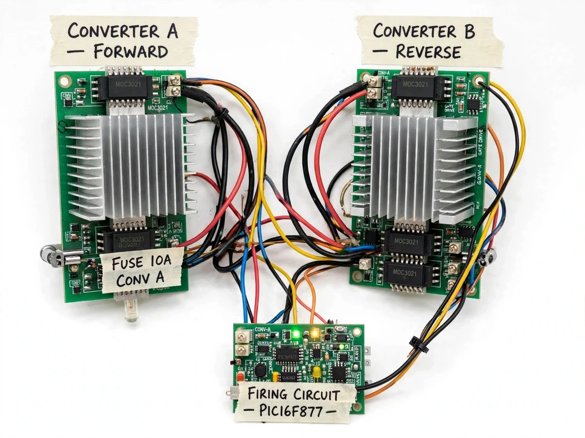
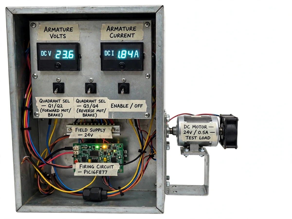
Industrial DC drives must do more than spin a motor in one direction: cranes, rolling mills and electric traction need controlled braking and quick reversal, which means the drive has to handle power flow in both directions — the four quadrants of the voltage-current plane. Textbook dual-converter diagrams are easy to draw but hard to internalize, because students rarely see forward motoring, regenerative braking, reverse motoring and reverse braking produced by one piece of hardware. This project closes that gap with a bench-top dual-converter drive: two antiparallel single-phase thyristor bridges feed a fractional-HP DC motor, and a microcontroller-based firing controller sets the firing angle for each converter through an interlocked quadrant selector, so every operating mode can be switched live and observed on panel meters.
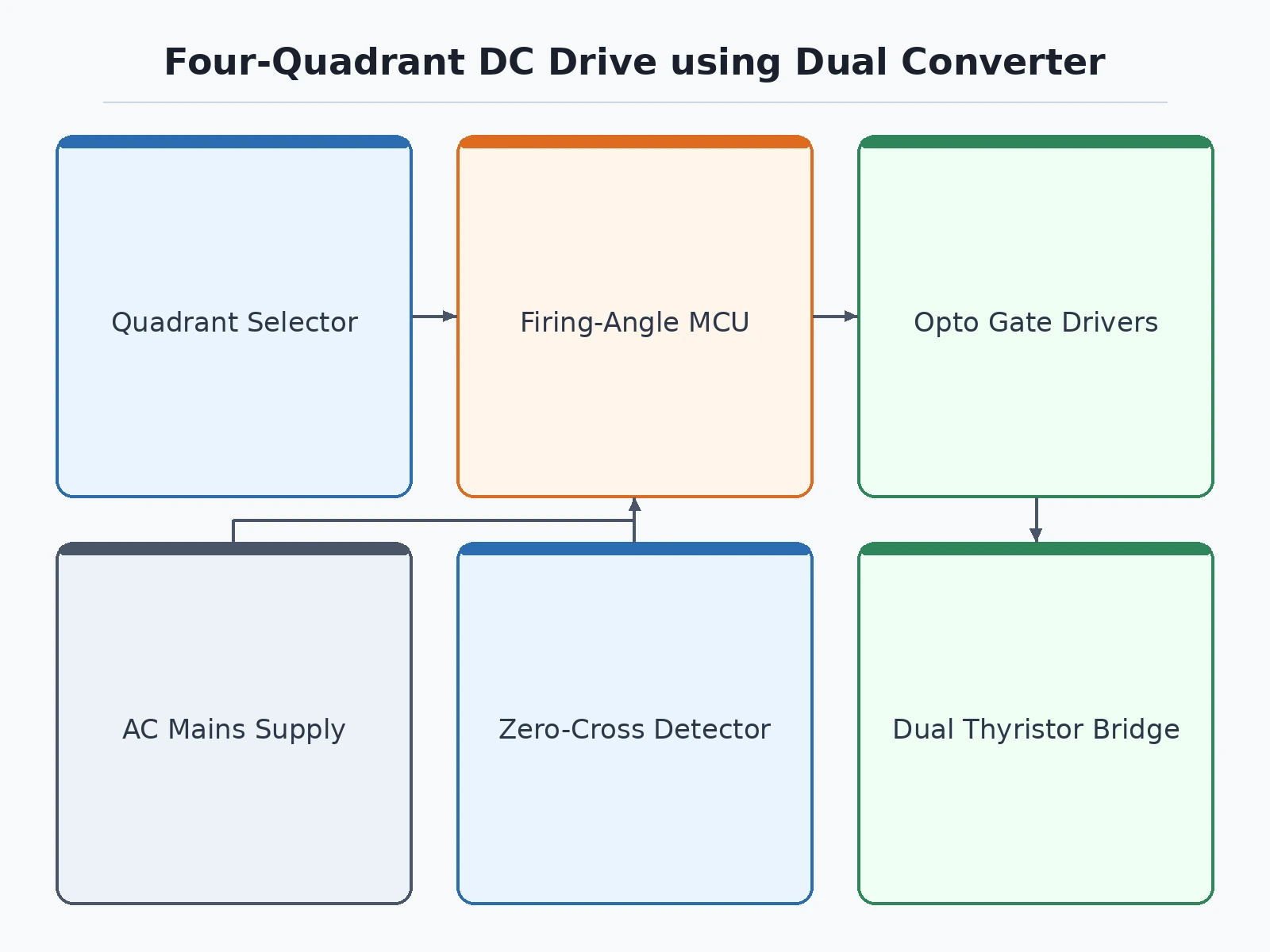
Selects the quadrant: forward/reverse motoring or braking.
Follow the working sequence
How it works
- A stepped-down AC supply feeds two antiparallel thyristor bridges — converter P for positive and converter N for negative armature voltage.
- A zero-crossing detector synchronizes the microcontroller to the mains so gate pulses fire at the correct angle every half-cycle.
- The user selects a quadrant on the panel: forward-motoring, forward-braking, reverse-motoring or reverse-braking.
- The controller fires the active converter at the set firing angle; the interlocked changeover keeps the idle converter fully off to avoid circulating current.
- In motoring quadrants the bridge rectifies AC to drive the motor; in braking quadrants the motor's back-EMF drives current back through the bridge in inverter mode, returning energy toward the supply.
- Panel meters show armature voltage and current with polarity, identifying the live quadrant from their signs.
Tech stack:
- Single-phase dual thyristor converter (antiparallel bridges)
- Microcontroller firing-angle controller with zero-crossing detection
- Opto-isolated gate drive via pulse transformers
- Fractional-HP DC motor as the drive load
- Digital panel meters (DC voltage, DC current)
| Parameter | Value |
|---|---|
| Topology | Single-phase dual converter, antiparallel full-wave thyristor bridges |
| Input | 230 V AC stepped down through an isolation transformer to a safe lab-level tap |
| Firing control | Microcontroller + zero-cross detector; firing angle adjustable 0–180° |
| Quadrant changeover | Interlocked break-before-make selector (non-circulating-current scheme) |
| Load | Fractional-HP DC motor, rating matched to the converter build |
| Metering | Panel meters for armature voltage and current with polarity |
| Braking | Regenerative — braking energy returned toward the supply side |
| Protection | Line fuses, RC snubbers, interlocked changeover |
Project features
- [Dual antiparallel converters] Two single-phase thyristor bridges connected back-to-back across the motor armature — one dedicated to positive and one to negative armature voltage.
- [Four-quadrant selector] Interlocked forward/reverse and motor/brake switches move the drive through all four quadrants, with a break-before-make changeover that keeps the two converters from shorting the supply.
- [Firing-angle controller] A microcontroller with zero-crossing detection generates synchronized gate pulses; the firing angle is adjustable from 0–180° to vary the average armature voltage.
- [Regenerative braking demo] In the braking quadrants the motor acts as a generator and returns power toward the AC supply side, demonstrating true regeneration instead of dissipative braking.
- [Live quadrant metering] Digital panel meters display armature voltage and current with polarity, so the operating quadrant reads directly from the signs of V and I.
- [Protection built in] Line fuses, RC snubbers across the thyristors and the interlocked changeover protect the bridges during quadrant switching.
- [Optional closed-loop speed control] A tacho-generator feedback loop with PI control can be added as a customization for tighter speed regulation under varying load.
What is included
- Working dual-converter drive panel with firing controller and motor rig
- Firmware source for the firing-angle controller
- Circuit and wiring documentation, component list
- Operating procedure for demonstrating each quadrant
- Project report PDF (theory, dual-converter analysis, waveforms, quadrant table)
- PPT presentation for final review
- Viva Q&A preparation document (four-quadrant operation, firing angle, regeneration, interlocking)
- Setup and safety guide
Advantages
- Two antiparallel single-phase thyristor bridges give one converter for positive and one for negative armature voltage across a single motor.
- Interlocked forward/reverse and motor/brake switches move the drive through all four quadrants, with a break-before-make changeover that keeps the two converters from shorting the supply.
- The microcontroller firing-angle controller with zero-crossing detection varies average armature voltage over a 0–180° firing-angle range.
- In the braking quadrants the motor acts as a generator and returns power toward the AC supply side, demonstrating true regeneration instead of dissipative braking.
- Digital panel meters display armature voltage and current with polarity, so the operating quadrant reads directly from the signs of voltage and current.
Disadvantages
- This is a low-power laboratory model, not an industrial drive, and it must not be connected to high-power machinery.
- The stepped-down supply keeps terminal voltages at safe lab levels, so the build demonstrates the control principle, not full mains-voltage operation.
- Quadrant changeover uses a non-circulating-current scheme, so there is a brief dead time during reversal, and bumpless reversal needs circulating-current control as a customization.
- Regenerative energy returns to the lab supply side, so the demonstration needs a supply and transformer arrangement that can absorb it.
- Thyristor converters draw harmonic currents, so the panel is intended for short laboratory demonstrations, not continuous connection without filtering.
Limitations & prerequisites
- This is a low-power laboratory model; it is not an industrial drive and must not be connected to high-power machinery.
- The stepped-down supply keeps terminal voltages at safe lab levels — the build demonstrates the control principle, not full mains-voltage operation.
- Quadrant changeover uses a non-circulating-current scheme, so there is a brief dead time during reversal; bumpless reversal needs circulating-current control, available as a customization.
- Regenerative energy returns to the lab supply side — the demonstration needs a supply and transformer arrangement that can absorb it, documented in the setup guide.
- Thyristor converters draw harmonic currents; the panel is intended for short laboratory demonstrations, not continuous connection without filtering.
- The base build uses open-loop firing-angle control, so speed regulation under load variation is limited unless the closed-loop option is added.
Frequently Asked Questions
Which controller is used?
A microcontroller-based firing controller synchronized to the mains through a zero-crossing detector, generating gate pulses for both thyristor bridges with an adjustable firing angle.
How are the four quadrants demonstrated?
An interlocked selector switches between forward/reverse and motoring/braking. Panel meters show armature voltage and current with polarity — the sign combination identifies the live quadrant.
Is the braking really regenerative?
Yes — in the braking quadrants the motor acts as a generator and the bridge operates in inverter mode, returning energy toward the supply side instead of wasting it in resistors.
What are the main limitations?
Low-power lab model; brief dead time during quadrant changeover (non-circulating-current scheme); open-loop speed control in the base build; the regenerative demo needs a supply that can absorb the returned energy.
What power supply is needed?
A standard 230 V AC lab outlet; the panel's own isolation transformer steps it down to safe demonstration levels.
Is this project suitable for a final-year project?
Yes — for Electrical Engineering programs. It demonstrates power electronics, converter control, four-quadrant operation and regenerative braking on hardware students can operate and measure. Suitable for B.E./B.Tech final-year projects in Electrical Engineering.
Components & software requirements
- Single-phase dual thyristor converter (antiparallel bridges)
- Microcontroller firing-angle controller with zero-crossing detection
- Opto-isolated gate drive via pulse transformers
- Fractional-HP DC motor as the drive load
- Digital panel meters (DC voltage, DC current)
Delivery information
Built-to-order project. Delivery timeline is shared after order confirmation based on current queue.
Support terms
Complete documentation, setup guide, and viva preparation included. Support for setup and explanation provided.
Download free synopsis (PDF)
Enter your name and WhatsApp number — the synopsis PDF downloads immediately. We may send occasional project updates on WhatsApp; no spam.
Microcontroller based 4 Quadrant Trainer for Drives (IOSR Journal of Engineering, 2012)