
More project photos (2)
The problem
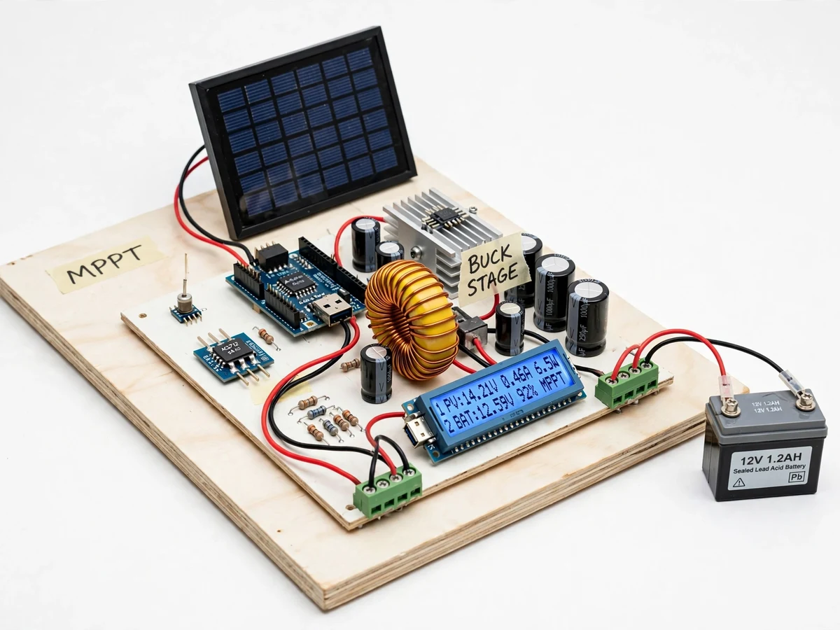
Solar photovoltaic panels have a characteristic I-V curve with a single maximum power point (MPP) that shifts with irradiance and cell temperature. A panel connected directly to a battery is forced to operate at the battery voltage, which is rarely the MPP — on a cold bright morning the mismatch can waste a third or more of the available energy. Maximum power point tracking solves this with a DC-DC converter whose duty cycle is continuously adjusted to hold the panel at its MPP while delivering the right charging voltage to the battery. Commercial MPPT controllers do this with dedicated chips, but the algorithm is very teachable on a microcontroller. This project builds one from first principles: an Arduino measures panel voltage and current, runs the perturb-and-observe (P&O) algorithm, and drives a buck converter MOSFET stage, implementing a full 3-stage lead-acid charging profile with battery protection — a complete, demonstrable solar power-electronics build.
How it works
- The solar panel feeds the buck converter input; voltage and current sensors (divider + Hall/ACS-type sensor) report panel V and I to the Arduino.
- The firmware computes panel power (P = V × I) and runs the perturb-and-observe loop: it steps the PWM duty cycle, re-measures power, and keeps stepping in the direction that increases power.
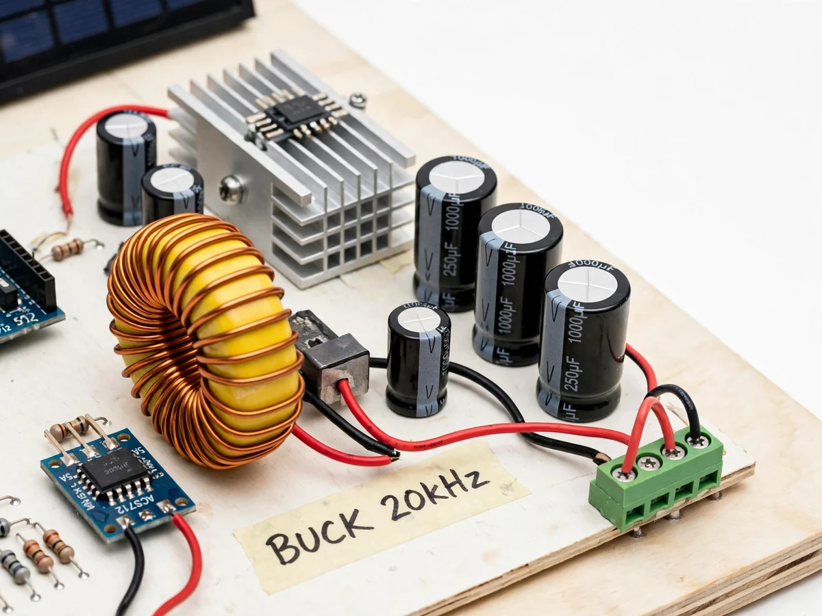
- The buck MOSFET, driven through a gate driver, converts the panel's MPP voltage down to the battery charging voltage at the commanded duty cycle.
- A second voltage sense on the battery selects the charging stage: bulk delivers the full tracked current, absorption holds constant voltage, float maintains a trickle.
- If the battery reaches full charge or the panel input disappears (night), charging stops and the blocking stage prevents reverse current.
- The load output stays connected until battery voltage falls to the low-voltage cut-off, then disconnects and re-engages with hysteresis.
- The LCD continuously shows panel V/I/P, battery voltage, active stage and duty cycle.
Tech stack:
- Arduino Uno/Nano (ATmega328P)
- Buck converter power stage (N-channel MOSFET, inductor, Schottky diode, capacitors)
- MOSFET gate driver
- Voltage dividers + Hall-effect current sensor (panel and battery sides)
- 16x2 character LCD
- Arduino IDE (C/C++ firmware)
- 12 V lead-acid battery and solar panel test rig
| Parameter | Value |
|---|---|
| Controller | Arduino Uno/Nano (ATmega328P), P&O loop in firmware |
| Panel input | Design range up to ~22 V open-circuit (typical 20–50 W test panel class) |
| Battery | 12 V lead-acid (SMF); setpoints adjustable in firmware |
| Converter | Buck stage, MOSFET switched at tens of kHz (exact frequency set in firmware) |
| Charging profile | Bulk (CC) → absorption (CV) → float; low-voltage load disconnect with hysteresis |
| Display | 16x2 LCD: panel V/I/P, battery V, stage, duty cycle |
| Tracking | Perturb-and-observe with configurable step size and sampling interval |
| Efficiency | Design target ~90–95% converter efficiency at nominal load (not measured at build) |
Project features
- [Perturb-and-observe MPPT] The firmware continuously nudges the buck duty cycle, compares panel power before and after, and climbs toward the maximum power point — the classic P&O algorithm, fully documented and tunable.
- [Buck converter power stage] A MOSFET buck stage with inductor, Schottky diode and output capacitors steps the panel voltage down to battery level at high switching frequency.
- [3-stage battery charging] Bulk (constant current), absorption (constant voltage) and float stages implement a proper lead-acid charging profile instead of crude on/off charging.
- [Live telemetry on LCD] Panel voltage, current and power plus battery voltage, charging stage and duty cycle are displayed on a 16x2 LCD, so the examiner can see tracking respond to shading the panel.
- [Load disconnect protection] The battery is disconnected from the load output at the low-voltage cut-off and reconnected with hysteresis, demonstrating deep-discharge protection.
- [Reverse and blocking protection] A blocking diode/MOSFET arrangement prevents night-time battery discharge back through the panel.
- [Adjustable setpoints] Absorption voltage, float voltage and cut-off thresholds are firmware constants, adjustable for different battery chemistries during the student's own setup.
What is included
- Working MPPT charge controller prototype (Arduino, buck stage, sensors, LCD, panel/battery test rig)
- Complete firmware source code (P&O tracking, 3-stage charging, protections, LCD)
- Circuit and wiring documentation with inductor/capacitor selection notes
- Component list with ratings
- Tuning procedure (buyer-run: set absorption/float voltages, verify tracking with shading tests)
- Project report PDF (PV characteristics, MPPT theory, buck design, methodology, test procedure)
- PPT presentation for final review
- Viva Q&A preparation document (MPP, P&O vs incremental conductance, buck operation, charging stages)
- Setup and demonstration guide
Limitations & prerequisites
- This is an academic demonstration prototype sized for a small test panel and battery; it is not a substitute for a rated commercial charge controller.
- Converter efficiency and tracking accuracy are design targets verified by the buyer's own tests — the prototype ships untuned and final values depend on the panel, inductor and layout used.
- The P&O algorithm oscillates slightly around the MPP and can be confused by very fast irradiance changes; this behavior is documented as a teaching point, not a defect fix.
- Lead-acid profile by default; lithium charging needs different setpoints and a proper BMS, noted as an extension.
- High-current paths need adequately rated wiring and the MOSFET needs heatsinking — thermal notes are included.
Frequently Asked Questions
What MPPT algorithm is used?
Perturb and observe (P&O): the firmware steps the buck duty cycle, measures the change in panel power, and keeps moving in the direction that increases power. Step size and sampling interval are tunable constants.
What battery does it charge?
A 12 V lead-acid battery with a 3-stage profile (bulk, absorption, float). Setpoints are firmware constants the student adjusts for their battery.
How do I demonstrate the tracking?
Partially shade the panel or change its angle during the demo — the LCD shows panel power dip and recover as the P&O loop finds the new maximum power point.
Can it charge lithium batteries?
Not as built — lithium needs a different voltage profile and cell-level protection (BMS). The report notes this as a documented extension.
What are the main limitations?
Small demo power level; efficiency and tracking figures are design targets verified by your own tests; P&O hunts slightly around the MPP by design.
Is this project suitable for a final-year project?
Yes — for Electrical programs. It combines PV characteristics, DC-DC conversion, control algorithms and battery management in one demonstrable build. Suitable for B.E./B.Tech final-year projects in Electrical engineering.
Components & software requirements
- Arduino Uno/Nano (ATmega328P)
- Buck converter power stage (N-channel MOSFET, inductor, Schottky diode, capacitors)
- MOSFET gate driver
- Voltage dividers + Hall-effect current sensor (panel and battery sides)
- 16x2 character LCD
- Arduino IDE (C/C++ firmware)
- 12 V lead-acid battery and solar panel test rig
Delivery information
Built-to-order project. Delivery timeline is shared after order confirmation based on current queue.
Support terms
Complete documentation, setup guide, and viva preparation included. Support for setup and explanation provided.