
More project photos (2)
The problem
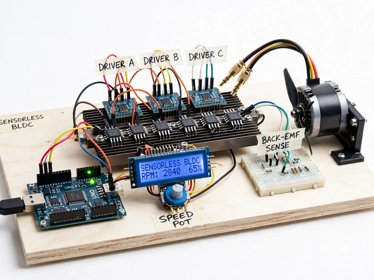
BLDC motors dominate drones, EVs, pumps and appliances because they combine DC-like control with AC-motor robustness — but they cannot run on plain DC: the stator windings must be energized in a rotating sequence synchronized to the rotor position. The usual answer is Hall-effect sensors inside the motor; the sensorless answer is to exploit the motor itself as the sensor. As the rotor's magnets sweep past the un-energized winding, they induce a back-EMF whose zero-crossing marks the exact commutation instant. Sensorless control reads this signal, filters it, and commutates from it — cheaper, more robust, and a genuinely instructive control problem because the scheme must start the motor blind (no back-EMF at standstill) and hand over to closed-loop sensing once spinning. This project implements that full cycle on an Arduino driving a 3-phase bridge.
How it works
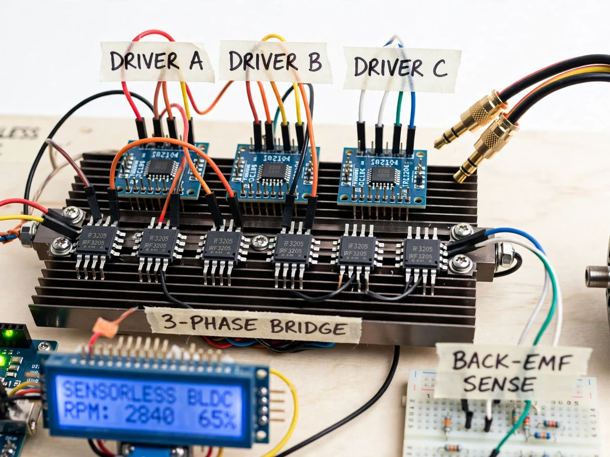
- The 3-phase MOSFET bridge energizes two of the three motor windings at a time in the six-step sequence, leaving the third floating.
- The back-EMF induced in the floating winding is divided down and compared against a virtual neutral point built from the three phases.
- Each zero-crossing of this signal marks 30 electrical degrees before the ideal commutation instant; a timer schedules the next step from it.
- At standstill there is no back-EMF, so the firmware first runs a timed open-loop ramp, increasing commutation frequency until the motor spins fast enough for reliable zero-cross detection.
- Control then hands over to closed-loop sensorless commutation, with the potentiometer setting the PWM duty cycle (speed).
- Commutation frequency is converted to RPM and displayed on the LCD with the duty cycle and direction.
- Overcurrent or loss of commutation feedback triggers shutdown with a fault indication until reset.
Tech stack:
- Arduino Uno/Nano (ATmega328P)
- 3-phase MOSFET bridge with gate drivers
- Back-EMF sensing network (dividers + virtual neutral)
- Comparator/ADC zero-cross detection in firmware
- Current sensing for overcurrent protection
- 16x2 character LCD
- Arduino IDE (C/C++ firmware)
- Sensorless BLDC test motor with coupled demo load
| Parameter | Value |
|---|---|
| Controller | Arduino Uno/Nano (ATmega328P) |
| Motor | Sensorless 3-phase BLDC test motor (rating matched to bridge; exact model in build notes) |
| Commutation | Six-step, sensorless via back-EMF zero-crossing vs virtual neutral |
| Start-up | Open-loop timed ramp with handover to closed-loop sensing (design behavior) |
| Speed control | Potentiometer-set PWM duty cycle; direction switch |
| Display | 16x2 LCD: RPM (from commutation frequency), duty cycle, state/fault |
| Protections | Overcurrent foldback/trip; stall/loss-of-feedback shutdown |
| Speed range | Approximate — depends on motor and supply; characterized by the buyer during setup |
Project features
- [Back-EMF zero-crossing commutation] The floating phase's back-EMF is compared against a virtual neutral; each zero-crossing schedules the next commutation — true sensorless operation with no Hall sensors.
- [Open-loop start-up ramp] From standstill the firmware runs a timed open-loop commutation ramp that spins the motor up until back-EMF is strong enough for closed-loop handover, demonstrating the classic sensorless start problem.
- [PWM speed control] A potentiometer sets the duty cycle applied to the bridge, giving smooth speed control across the motor's range.
- [Direction control] A switch reverses the commutation sequence for bidirectional running.
- [Overcurrent limiting] Phase current sensing folds back or trips the drive on overcurrent, protecting the MOSFETs during stalls.
- [RPM display on LCD] Speed is computed from the commutation frequency and shown on a 16x2 LCD alongside duty cycle and running state.
- [Stall detection] If commutation feedback is lost (locked rotor), the drive shuts down instead of cooking the windings.
What is included
- Working sensorless BLDC controller prototype (Arduino, 3-phase bridge, sensing network, LCD, test motor)
- Complete firmware source code (start-up ramp, zero-cross commutation, PWM, protections, LCD)
- Circuit and wiring documentation with bridge and sensing design notes
- Component list with voltage/current ratings
- Tuning procedure (buyer-run: set ramp profile, verify handover, calibrate RPM display)
- Project report PDF (BLDC theory, sensorless principles, methodology, test procedure)
- PPT presentation for final review
- Viva Q&A preparation document (back-EMF, six-step commutation, virtual neutral, sensorless start problem)
- Setup and demonstration guide
Limitations & prerequisites
- This is an academic demonstration drive at modest power; it is not an EV or industrial servo drive.
- Start-up reliability, speed range and handover behavior are design behaviors tuned by the buyer's own procedure — the drive ships with default constants, not measured performance.
- Sensorless control has weak low-speed torque by principle; precise low-speed positioning needs sensored control, noted as a documented limitation.
- The exact RPM and current figures depend on the motor and supply used; the report gives the measurement method rather than pre-claimed numbers.
- Sustained stall or overload needs the thermal and current notes followed; the MOSFETs need heatsinking.
Frequently Asked Questions
How does sensorless commutation work without Hall sensors?
The un-energized winding generates back-EMF as the rotor magnets pass it. Detecting each zero-crossing of that signal against a virtual neutral gives the rotor position timing needed to commutate — the motor becomes its own sensor.
How does the motor start if there is no back-EMF at standstill?
With an open-loop timed ramp: the firmware commutates on a fixed accelerating schedule until the motor spins fast enough for back-EMF to be readable, then hands over to closed-loop sensing.
What speed control does it offer?
A potentiometer sets the PWM duty cycle for smooth speed control, plus a direction switch. RPM is computed from commutation frequency and shown on the LCD.
Can it do precise low-speed positioning?
No — sensorless six-step control is inherently weak at very low speed. That limitation is documented; servo-grade positioning needs sensored (Hall/encoder) control.
What are the main limitations?
Demo-scale power; start-up and speed figures are design behaviors you tune yourself; weak low-speed torque by principle; no pre-measured performance claims.
Is this project suitable for a final-year project?
Yes — for Electrical programs. Sensorless commutation, back-EMF sensing and the start-up handover problem are excellent motor-control viva material. Suitable for B.E./B.Tech final-year projects in Electrical engineering.
Components & software requirements
- Arduino Uno/Nano (ATmega328P)
- 3-phase MOSFET bridge with gate drivers
- Back-EMF sensing network (dividers + virtual neutral)
- Comparator/ADC zero-cross detection in firmware
- Current sensing for overcurrent protection
- 16x2 character LCD
- Arduino IDE (C/C++ firmware)
- Sensorless BLDC test motor with coupled demo load
Delivery information
Built-to-order project. Delivery timeline is shared after order confirmation based on current queue.
Support terms
Complete documentation, setup guide, and viva preparation included. Support for setup and explanation provided.