
More project photos (2)
The problem
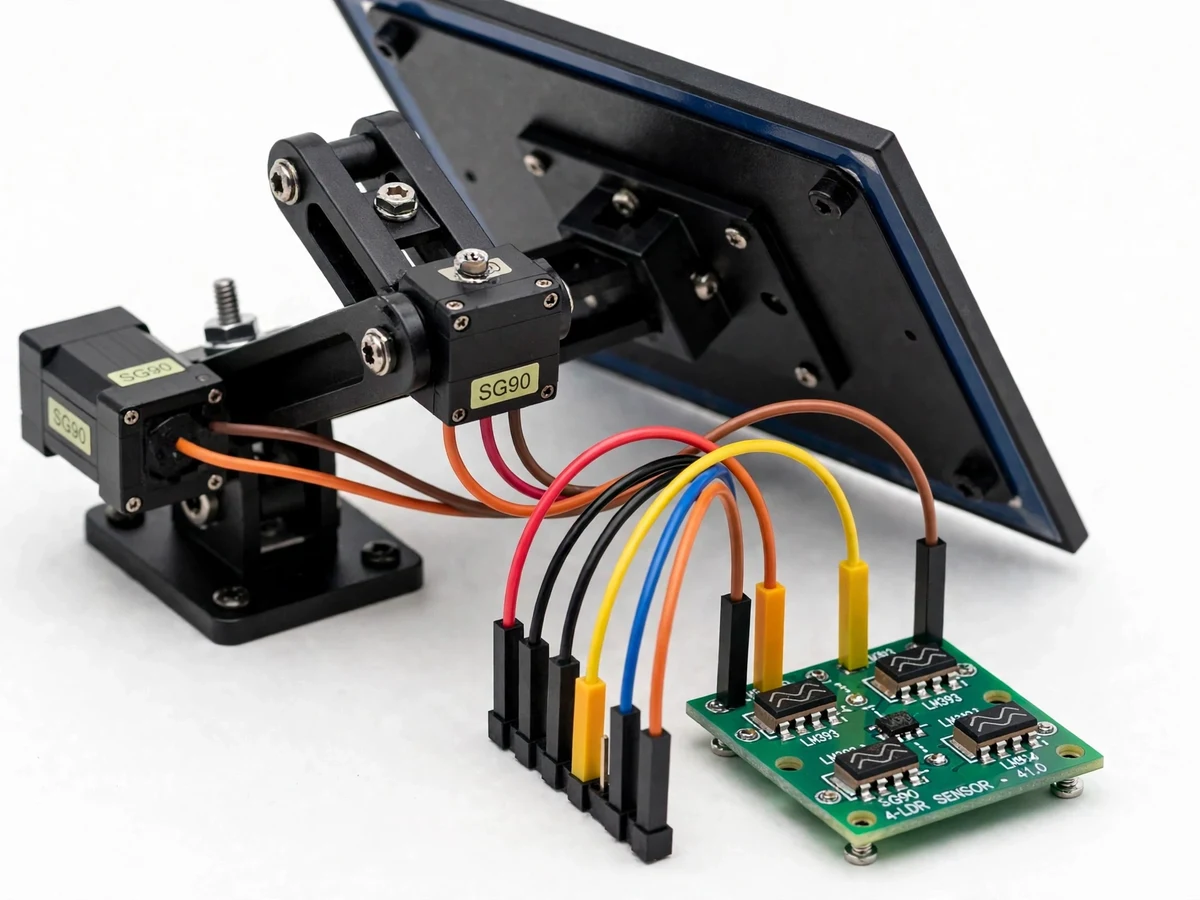
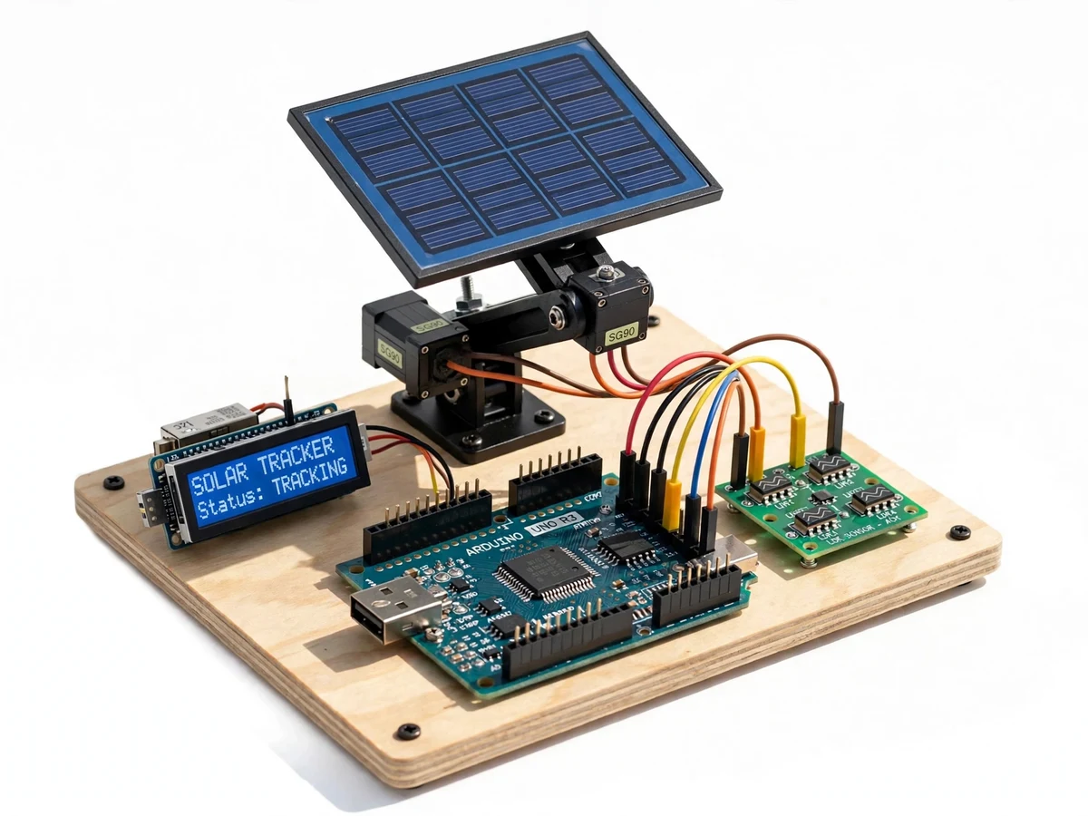
A fixed solar panel only faces the sun directly for a short part of the day; the rest of the time the light arrives at an angle and the cosine law quietly eats the output. Utility plants solve this with trackers, but students usually meet tracking only as a textbook diagram — the sensing, the control loop and the mechanical drive are never in their hands. The gap is a bench-scale tracker that demonstrates the full loop honestly: light sensing with a real sensor array, a control algorithm the student can read and tune, and a two-axis drive they assembled. This project builds it: a small PV panel on a pan-tilt mount, four LDRs arranged in quadrants behind a cross-shaped shade divider, an Arduino comparing the quadrant pairs, and two servos (or a servo + linear actuator) driving azimuth and elevation. A sensing stage measures panel voltage and current so tracked and fixed readings can be compared side by side.
How it works
- The four LDRs continuously report light levels; the shade divider makes the bright-side pair read higher.
- The Arduino averages and compares the quadrant pairs to compute the azimuth and elevation error.
- If the error exceeds the deadband, the corresponding servo steps the panel toward the brighter direction.
- The loop repeats at the configured interval, keeping the panel normal to the brightest sky region through the day.
- At dusk the dark-detection logic parks the panel east for the next dawn; at dawn tracking resumes automatically.
- During the comparison experiment the student logs panel voltage/current alongside a fixed reference panel, producing their own tracked-vs-fixed dataset.
Tech stack:
- Arduino-class microcontroller
- 4-LDR quadrant sensor array with cross shade divider
- 2 servo motors (azimuth + elevation pan-tilt mount)
- Small PV panel (design 5–10 W class) + fixed reference panel
- Voltage/current sensing stage (divider + shunt/ACS-type sensor)
- Push-button manual jog controls, 16x2 LCD status
- Arduino IDE (C/C++ firmware)
- Outdoor-rated mounting pole/base hardware
| Parameter | Value |
|---|---|
| Sensing | 4-LDR quadrant array with cross divider; differential comparison |
| Axes | Azimuth + elevation, servo-driven pan-tilt mount |
| Control | Deadband logic, configurable; dark-park homing for night |
| Panel | Small PV panel, design 5–10 W class; fixed reference panel for comparison |
| Measurement | Panel voltage + current sensing for tracked-vs-fixed logging |
| Modes | Auto track, manual jog, night park, wind-stow (manual command) |
| Gain claim | None at build — the student measures and reports their own comparison data |
| Mounting | Pole/base hardware for terrace or lab-roof placement |
Project features
- [4-LDR quadrant sensing] LDRs behind a cross divider see differential light; the Arduino compares left/right and up/down pairs to find the brightest direction.
- [Dual-axis drive] Two servos move the panel in azimuth and elevation, giving full-sky following instead of the single-axis compromise.
- [Deadband control logic] A configurable deadband stops hunting and jitter around the setpoint; the student tunes it and observes the trade-off with tracking responsiveness.
- [Night/sleep behavior] When all LDRs read dark, the controller parks the panel at the east-facing dawn position — the same homing logic real trackers use.
- [Panel output logging] Voltage and current sensing lets the student log tracked-panel output against a fixed reference panel under identical conditions.
- [Manual override mode] Push-buttons allow manual jogging of both axes for calibration and for demonstrating the mechanism independent of the sun.
- [Wind-safe stow option] Firmware supports a stow position command (flat/horizontal) as a documented manual action for the report's discussion section.
What is included
- Working dual-axis tracker prototype (mount, servos, LDR array, panel, sensing)
- Complete firmware source code (quadrant logic, deadband, homing, manual mode)
- Fabrication and assembly documentation
- Circuit and wiring documentation
- Tracked-vs-fixed comparison experiment procedure with logging sheets
- Component list with ratings
- Project report PDF (PV theory, tracking geometry, methodology, student's own data)
- PPT presentation for final review
- Viva Q&A preparation document (cosine losses, LDR characteristics, servo control)
- Setup and demonstration guide
Limitations & prerequisites
- No efficiency-gain numbers are claimed at build — published tracker-gain figures vary wildly with location and weather, and the student's own measured comparison is the only honest number in the report.
- LDRs are slow, temperature-sensitive and spectrally mismatched to PV cells; the report must acknowledge them as a teaching sensor, not a precision sun sensor.
- Servos draw holding current and have limited torque; the panel size is matched to the servo rating and must not be upsized without re-checking the mechanics.
- The rig is a lab/rooftop demonstrator, not a weatherproof product — rain, dust and wind loading are outside its design envelope (the wind-stow is a manual, documented action).
- Tracking needs direct sun; on overcast days the bright-spot logic wanders and the comparison experiment must be run on clear days, which the procedure states.
Frequently Asked Questions
How does it find the sun?
Four LDRs in quadrants behind a cross divider: the brighter side reads higher, and the Arduino drives the two servos until the pairs balance — no clock, GPS or astronomical math needed.
Why dual-axis instead of single?
Single-axis tracks only the east-west arc; the elevation axis also follows the seasonal/ daily height change of the sun, which is the point of the comparison experiment.
How much more power does tracking give?
That is your experiment, not a claimed number: the kit includes a fixed reference panel and a logging procedure so you measure tracked-vs-fixed output under your own sky and report it.
What happens at night?
Dark detection parks the panel facing east; tracking resumes automatically at dawn.
Can it survive wind and rain?
It is a lab/rooftop demonstrator, not a weatherproof product; the firmware includes a manual wind-stow command, and the limitations document the envelope honestly.
Is this project suitable for a final-year project?
Yes — for Electrical and Electronics programs. It demonstrates PV fundamentals, sensor-based control, servo mechanics and honest experimental comparison. Suitable for B.E./B.Tech final-year projects in Electrical and Electronics engineering.
Components & software requirements
- Arduino-class microcontroller
- 4-LDR quadrant sensor array with cross shade divider
- 2 servo motors (azimuth + elevation pan-tilt mount)
- Small PV panel (design 5–10 W class) + fixed reference panel
- Voltage/current sensing stage (divider + shunt/ACS-type sensor)
- Push-button manual jog controls, 16x2 LCD status
- Arduino IDE (C/C++ firmware)
- Outdoor-rated mounting pole/base hardware
Delivery information
Built-to-order project. Delivery timeline is shared after order confirmation based on current queue.
Support terms
Complete documentation, setup guide, and viva preparation included. Support for setup and explanation provided.