
More project photos (3)
The problem
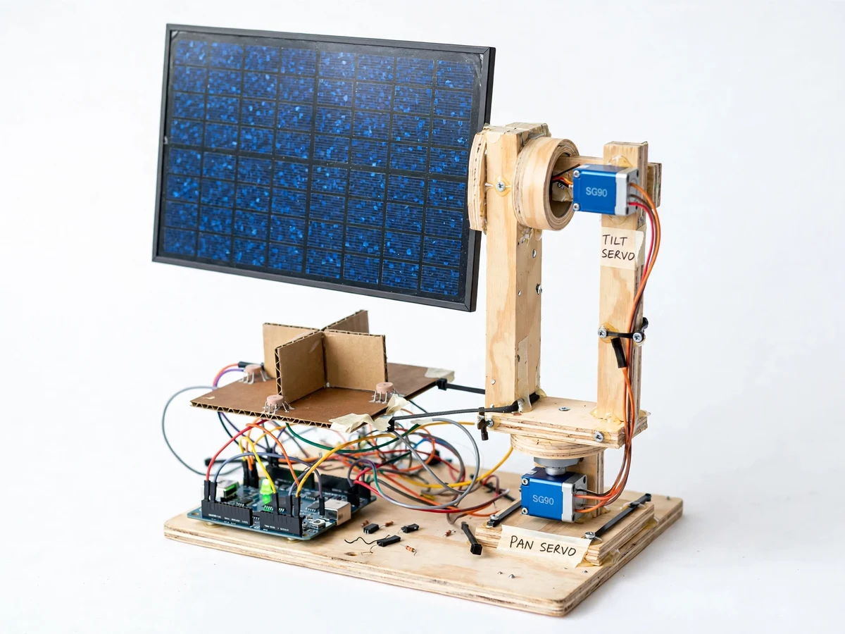
A fixed solar panel spends most of the day misaligned with the sun: it faces one direction while the sun arcs across the sky, so the angle of incidence is only near-ideal for a short window around noon. The physics is simple — a panel collects most when sunlight strikes it close to perpendicular — and solar farms recover that lost window with tracking mounts that follow the sun. But commercial trackers are expensive closed systems, and in college labs the tracking principle is usually only a diagram on a slide. This project makes it tangible: a working dual-axis tracker built from a small PV panel, four LDR sensors, two hobby servos and an Arduino. The student builds the gimbal, wires the sensor bridge, writes the tracking logic with hysteresis, and runs the calibration procedure — learning feedback control, sensor differential measurement and mechanical drive design in one build.
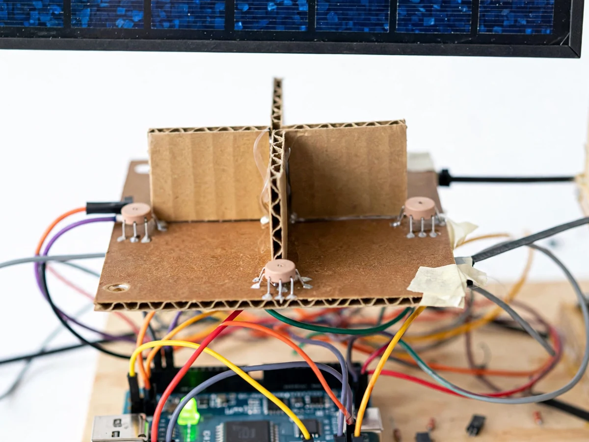
Four LDRs in a cross pattern with a shadow divider; off-sun alignment shades some sensors.
Follow the working sequence
How it works
- Four LDRs sit in a cross pattern on a small board, separated by a cardboard shadow divider; when the panel is off-sun, the divider shades some LDRs and the readings differ.
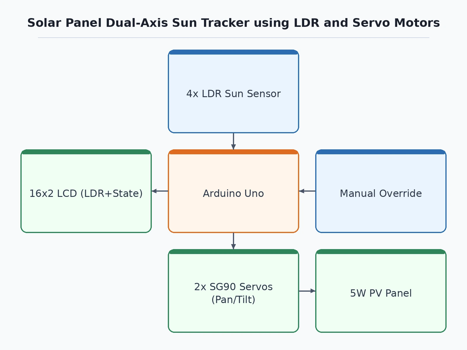
- The Arduino samples the four LDRs through voltage dividers and computes the left-right and top-bottom differences.
- If a difference exceeds the deadband, the firmware steps the corresponding SG90 servo toward the brighter side by a small increment.
- The loop repeats every few hundred milliseconds; when all pairs balance within the deadband, the panel holds — that is the sun-facing position.
- The cycle continues through the day, so the panel re-aims itself as the sun moves.
- In manual mode, serial commands or buttons drive each axis directly for testing and demonstration.
- The LCD continuously displays the four sensor values and the current axis positions.
Tech stack:
- Arduino Uno (ATmega328P)
- 4x LDR sensors in cross arrangement with shadow divider
- 2x SG90 servo motors (pan + tilt)
- Small polycrystalline PV panel (design approx. 5 W)
- Plywood dual-axis gimbal frame
- 16x2 character LCD
- Arduino IDE (C/C++ firmware)
- 5 V regulated power supply
| Parameter | Value |
|---|---|
| Tracking axes | 2 (pan + tilt), servo-driven |
| Sun sensor | 4x LDR in cross pattern with shadow divider |
| Actuators | 2x SG90 micro servos (design torque 1.8 kg-cm each) |
| Controller | Arduino Uno, differential-compare tracking loop |
| Panel (design) | Approx. 5 W polycrystalline, approx. 20 x 15 cm |
| Deadband | Configurable in firmware; set during buyer calibration |
| Modes | Automatic tracking + manual override |
| Display | 16x2 LCD: LDR readings + axis state |
| Power | 5 V DC regulated; panel output is for measurement, not grid use |
Project features
- [Dual-axis tracking] Pan and tilt axes let the panel follow the sun in both azimuth and elevation, unlike single-axis trackers that only correct one plane.
- [Four-LDR differential sensing] LDRs in a cross arrangement with a shadow divider compare light levels; the Arduino drives the axes until all four readings balance, which is the sun-facing position.
- [Servo-driven gimbal] Two SG90 servos move the panel through the wooden gimbal frame — a visible, examinable mechanism rather than a black box.
- [Deadband anti-hunting] Firmware compares sensor pairs against a configurable deadband so the servos settle instead of oscillating around the balance point.
- [Manual override mode] A push-button or serial command switches to manual positioning for viva demonstrations and for testing the mechanics without sunlight.
- [Live status readout] A 16x2 LCD shows the four LDR readings and the current pan/tilt state during operation.
- [Buyer-run calibration] The build ships with a calibration procedure: centering the servos, trimming LDR balance and setting the deadband on the student's own hardware.
What is included
- Working dual-axis sun tracker prototype (gimbal, panel, LDR board, servos, Arduino, LCD)
- Complete firmware source code (tracking loop, deadband, manual mode, LCD)
- Wiring and assembly documentation for the gimbal and sensor board
- Calibration procedure (servo centering, LDR trim, deadband setting)
- Project report PDF (tracking theory, sensor bridge design, methodology, test procedure)
- PPT presentation for final review
- Viva Q&A preparation document (feedback control, differential sensing, servo control)
- Setup and demonstration guide
Limitations & prerequisites
- Tracking gain is demonstrated by comparing panel output voltage at fixed vs tracked positions — no pre-claimed percentage improvement; results come from the student's own measurements.
- LDRs respond to visible light, so tracking needs direct sun; heavy cloud or indoor lighting gives weak differentials.
- SG90 servos limit the panel to small sizes; a larger panel would need higher-torque servos and a stronger frame, which is a possible extension.
- The prototype is for demonstration, not a rooftop installation — no weatherproofing, lightning protection or grid connection.
- Servo position is open-loop (no encoders), so long-term drift is corrected only by the sensor loop.
Frequently Asked Questions
How does the tracker find the sun?
Four LDRs in a cross with a shadow divider produce different readings when off-sun. The Arduino compares left-right and top-bottom pairs and steps the two servos toward the brighter side until all four balance — that balance point is the sun-facing position.
What stops the servos from jittering?
A configurable deadband in the firmware: the servos only move when a sensor-pair difference exceeds the deadband, so they settle at the balance point instead of hunting around it.
Can I demonstrate it indoors?
Partially — a bright lamp can create a differential for the sensor logic, but real tracking behavior needs direct sunlight, and the viva demo is designed around that.
What panel size can it carry?
The design panel is approx. 5 W (approx. 20 x 15 cm), matched to SG90 servo torque. Heavier panels need stronger servos and frame reinforcement.
What are the main limitations?
Needs direct sun, no measured gain claimed before the student measures it, open-loop servos, and it is a demonstration rig — not weatherproofed for rooftop use.
Is this project suitable for a final-year project?
Yes — for Mechatronics, Electrical and IoT programs. It demonstrates feedback control, differential sensing, servo mechanisms and calibration, all strong viva material. Suitable for B.E./B.Tech final-year projects in Mechatronics, Electrical and IoT engineering.
Components & software requirements
- Arduino Uno (ATmega328P)
- 4x LDR sensors in cross arrangement with shadow divider
- 2x SG90 servo motors (pan + tilt)
- Small polycrystalline PV panel (design approx. 5 W)
- Plywood dual-axis gimbal frame
- 16x2 character LCD
- Arduino IDE (C/C++ firmware)
- 5 V regulated power supply
Delivery information
Built-to-order project. Delivery timeline is shared after order confirmation based on current queue.
Support terms
Complete documentation, setup guide, and viva preparation included. Support for setup and explanation provided.
Download free synopsis (PDF)
Enter your name and WhatsApp number — the synopsis PDF downloads immediately. We may send occasional project updates on WhatsApp; no spam.