
More project photos (3)
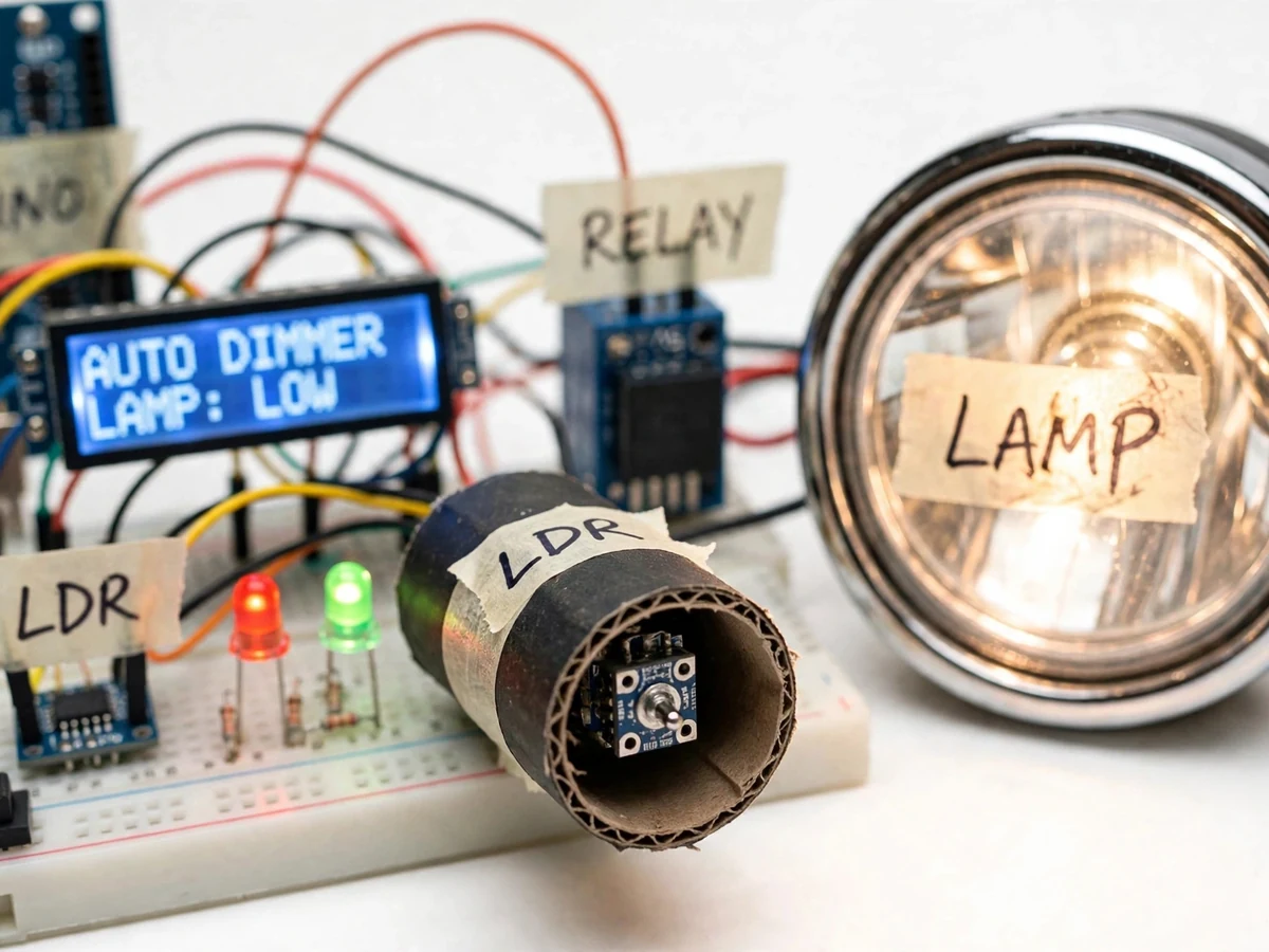
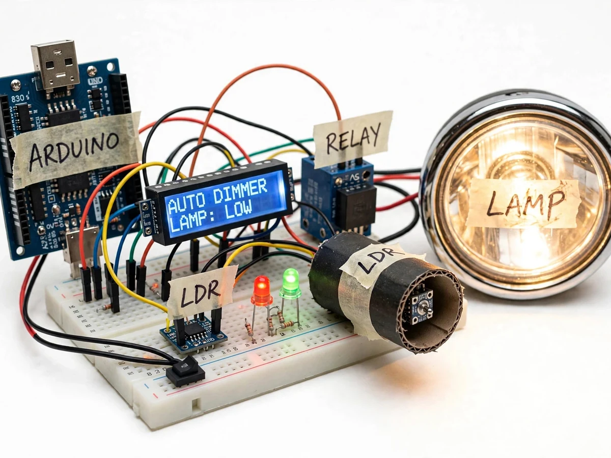
The problem
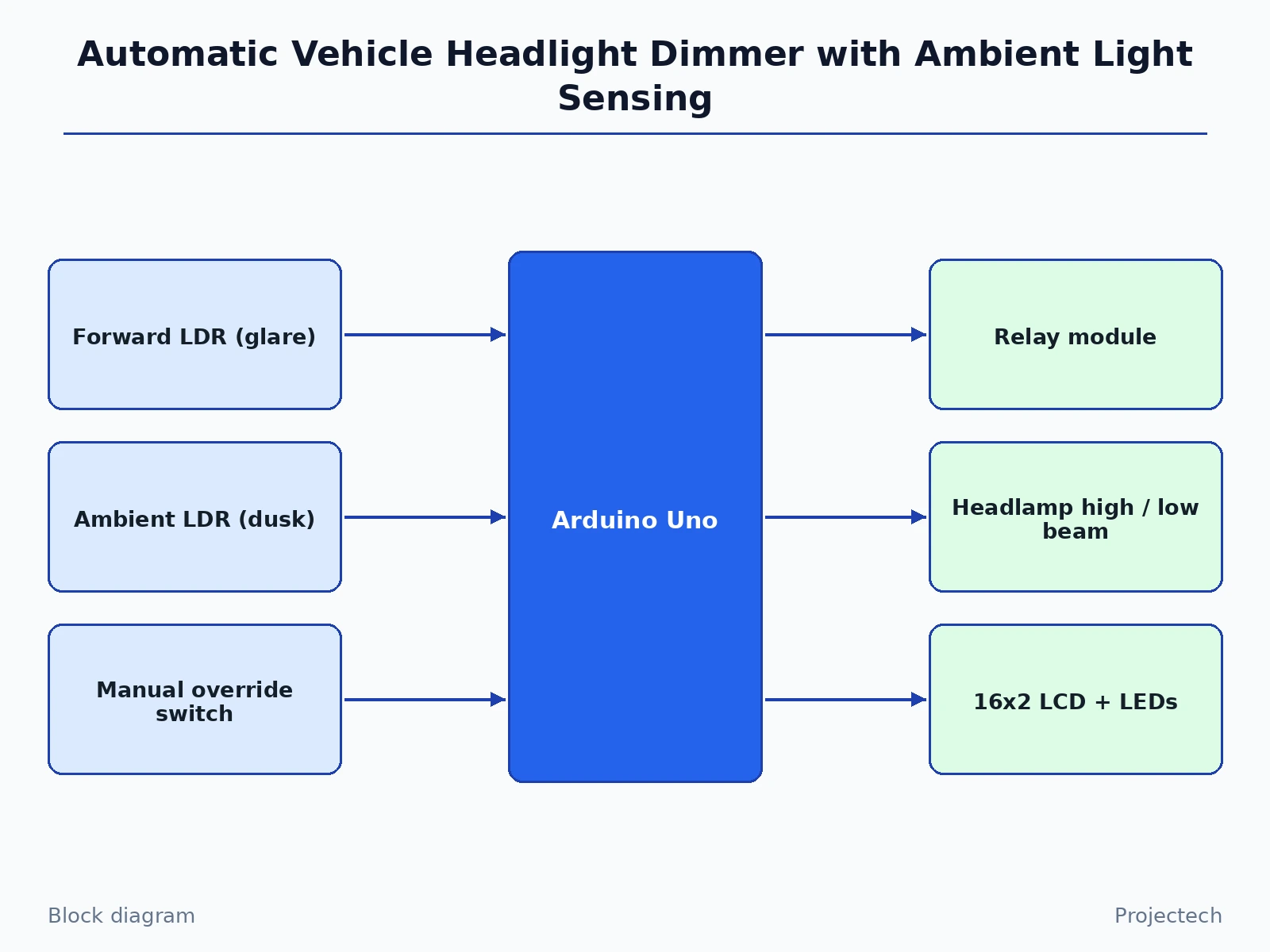
High-beam glare from oncoming traffic is a genuine road-safety hazard — momentary blindness at closing speeds leaves no margin — yet most drivers dip their beams late or not at all, out of inattention or forgetfulness. Automatic high-beam systems exist in premium cars as sealed modules; the sensing principle, however, is simple enough to build and fully understand as a student prototype. This project implements it with an Arduino: a forward-facing LDR behind a simple lens tube measures oncoming light intensity, and when it exceeds a student-calibrated threshold the controller switches the headlamp relay from high to low beam. A short hold delay prevents flicker when the oncoming vehicle passes through the sensor's edge, and an ambient-light LDR arms the system only after dusk so daytime driving is unaffected. The build demonstrates threshold-based control, relay switching of a real load, and anti-flicker timing logic on hardware.
Measures daylight; below the dusk threshold the automatic path arms.
Follow the working sequence
How it works
- The ambient LDR continuously measures daylight; below the dusk threshold the system arms, otherwise it stays in manual pass-through.
- When armed, the forward LDR is sampled every 100 ms; readings are smoothed with a short moving average to reject noise.
- If the smoothed glare reading exceeds the calibrated threshold, the Arduino de-energizes the high-beam relay contact, dropping the lamp to low beam, and lights the LOW indicator.
- When the reading falls back below the threshold minus a hysteresis margin, a hold timer (typically 2–3 seconds, design range) starts.
- If the road stays clear through the hold period, the relay re-engages high beam; any new glare during the hold restarts the wait.
- The hysteresis band plus the hold delay together prevent flicker at the threshold edge.
- The manual override switch, when engaged, bypasses the automatic path entirely and the LCD flags MANUAL mode.
Tech stack:
- Arduino Uno (ATmega328P)
- 2× LDR light sensors with dividers (glare + ambient)
- 5 V relay module (high/low beam switching)
- 12 V automotive-style headlamp demo unit
- 16×2 character LCD + status LEDs
- Manual override switch
- Arduino IDE (C/C++ firmware)
| Parameter | Value |
|---|---|
| Controller | Arduino Uno |
| Glare sensing | Forward LDR in lens tube, 100 ms sampling |
| Ambient sensing | Second LDR, dusk arming threshold |
| Switching | Relay, high/low beam select |
| Hold delay | 2–3 seconds typical (design range, configurable) |
| Hysteresis | Threshold ± margin band (calibrated) |
| Response time | Beam dip within approximately 300 ms of threshold crossing (design target) |
| Display | 16×2 LCD + beam-state LEDs |
| Power | 12 V DC (lamp + logic via regulator) |
Project features
- [Oncoming-glare sensing] A forward-facing LDR in a lens tube measures the intensity of oncoming headlights while rejecting most side and sky light.
- [Automatic high/low switching] The Arduino drives a relay that switches the headlamp between high and low beam filaments the moment glare crosses the calibrated threshold.
- [Anti-flicker hold delay] After the glare clears, the system waits a short hold period before restoring high beam, so a single passing vehicle does not cause rapid beam toggling.
- [Dusk-only arming] A second LDR measures ambient daylight and arms the dimmer only after dusk; daytime driving always stays on the driver's manual selection.
- [Manual override] A dashboard switch forces high or low beam regardless of the automatic logic, keeping the driver in ultimate control as road-safety practice requires.
- [Status indication] LEDs and a 16×2 LCD show the current beam state, sensor readings and whether the system is armed.
- [Student calibration] Both LDR thresholds are set by the student with a real headlamp at measured distances, logged on the calibration sheet — the trigger point is measured, not assumed.
What is included
- Working prototype: sensor head, controller, relay, demo headlamp, LCD
- Complete firmware (sampling, threshold logic, hysteresis, hold delay, override)
- LDR calibration procedure with distance-based log sheet
- Wiring diagram and 12 V automotive-style wiring notes
- Project report PDF (background, LDR sensing theory, control logic design, methodology)
- PPT presentation for final review
- Viva Q&A preparation document
Limitations & prerequisites
- This is a tabletop demonstrator with a 12 V demo lamp — it is not certified automotive equipment and must not be fitted to a real vehicle without proper automotive-grade engineering.
- The LDR responds to light intensity, not to vehicles: bright streetlights or reflective signs near the threshold can influence it, which is why calibration distance and the lens tube matter — the report discusses this honestly.
- Heavy rain or fog scatters oncoming light and changes the effective trigger distance; the system is a clear-weather demonstrator.
- The 100 ms sampling plus relay time gives a dip response of roughly 300 ms (design target) — adequate for demonstration, not a claim about production timing.
- Only one lamp channel is switched in the demo build; a real vehicle has two headlamps plus high-beam assist integration, listed as future scope.
Frequently Asked Questions
How does it detect an oncoming vehicle?
It does not detect vehicles — it detects their headlights. A forward-facing LDR measures light intensity ahead; when the smoothed reading crosses the calibrated threshold, the controller treats it as oncoming glare and dips the beam.
What stops the beam from flickering when a car passes?
Two things: a hysteresis band (the restore threshold sits below the trigger threshold) and a 2–3 second hold delay after the glare clears. Together they prevent rapid toggling at the edge.
Does it work in daytime?
No, by design. An ambient-light LDR arms the system only after dusk; in daylight the lamp follows the manual switch only.
Can the driver still control the beam?
Yes — a manual override switch forces high or low beam regardless of the automatic logic, and the LCD flags MANUAL mode. Driver authority is a deliberate design requirement.
How is the trigger threshold set?
By the student during calibration: a real headlamp is shone at the sensor from measured distances, readings are logged, and the threshold is picked from the data — documented on the calibration sheet.
Is this project suitable for a final-year project?
Yes — for Electronics, Electrical and IoT & Embedded programs. It demonstrates light sensing, threshold control with hysteresis, relay switching of a real load and anti-flicker timing on a road-safety application. Suitable for B.E./B.Tech final-year projects in Electronics, Electrical and IoT & Embedded Systems.
Components & software requirements
- Arduino Uno (ATmega328P)
- 2× LDR light sensors with dividers (glare + ambient)
- 5 V relay module (high/low beam switching)
- 12 V automotive-style headlamp demo unit
- 16×2 character LCD + status LEDs
- Manual override switch
- Arduino IDE (C/C++ firmware)
Delivery information
Built-to-order project. Delivery timeline is shared after order confirmation based on current queue.
Support terms
Complete documentation, setup guide, and viva preparation included. Support for setup and explanation provided.
Download free synopsis (PDF)
Enter your name and WhatsApp number — the synopsis PDF downloads immediately. We may send occasional project updates on WhatsApp; no spam.