
More project photos (2)
The problem
Most schools still ring the bell by hand — a peon watches a wall clock and pulls a switch, which means rings drift by minutes, get missed during busy mornings, and there is no record of whether the schedule was actually followed. Existing automatic bell timers are sealed boxes with cryptic button programming that teachers cannot change when the timetable shifts. This project builds an automatic bell system the honest way: an ESP32 paired with a DS3231 real-time clock (±2 ppm accuracy per its datasheet) keeps schedule time, compares it against a stored timetable every second, and switches a relay-driven bell or horn at each configured event. The timetable itself is edited from any phone or laptop on the local Wi-Fi through a simple web page — no apps, no cryptic menus — covering periods, short and long breaks, assembly, holidays and exam schedules. Because the schedule lives in flash memory and the RTC runs on a coin cell, a power cut does not disturb a single ring.
How it works
- The DS3231 RTC keeps calendar time on its coin cell, accurate to about ±2 ppm per its datasheet (roughly ±1 minute per year, design expectation).
- At power-up the ESP32 reads the timetable from flash memory and starts comparing it against RTC time once per second.
- The timetable is a list of events — time, day-of-week mask, bell pattern and duration — each stored as a compact record.
- When the current time matches an event and that day is not marked a holiday, the ESP32 energizes the relay for the configured pattern and duration, driving the bell or horn.
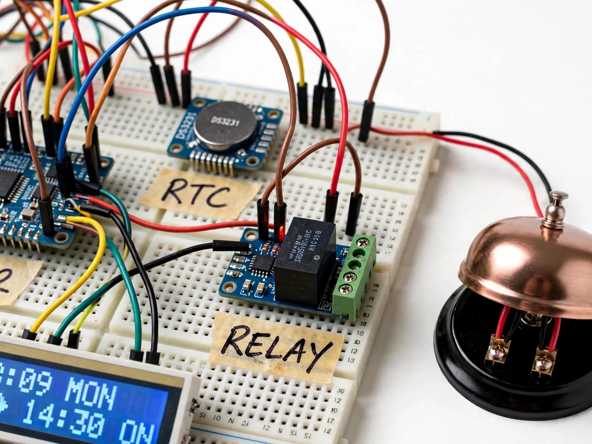
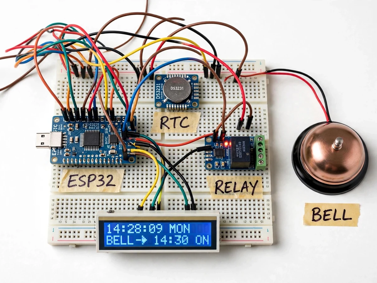
- The 16×2 LCD continuously shows current time, date and the next upcoming event.
- For configuration, the ESP32 hosts a web portal on the local Wi-Fi; staff edit events in a form and submit, and the firmware rewrites the flash timetable and returns to normal operation.
- The manual override button triggers a ring pattern immediately through a firmware interrupt path that never alters the stored schedule.
Tech stack:
- ESP32 development board (Wi-Fi)
- DS3231 real-time clock module with coin-cell backup
- 5 V relay module driving a bell/horn
- 16×2 character LCD
- PA horn / electric bell unit
- Arduino IDE (C/C++ firmware)
- HTML web portal (timetable configuration)
| Parameter | Value |
|---|---|
| Controller | ESP32 (Wi-Fi for configuration portal) |
| Timekeeping | DS3231 RTC, ±2 ppm (datasheet value) |
| Schedule capacity | Approximately 40 events (design target, flash-limited) |
| Ring timing accuracy | Within ±2 seconds of configured time (design target) |
| Bell patterns | 5 (class change, short break, long break, assembly, emergency) |
| Ring duration | Configurable, 1–30 seconds per event |
| Display | 16×2 character LCD |
| Power | 230 V AC bell circuit via relay; controller on 5 V adapter |
| Backup | CR2032 coin cell keeps RTC for approximately 2–3 years (datasheet expectation) |
Project features
- [RTC-driven scheduling] A DS3231 real-time clock (±2 ppm per datasheet) keeps time independently of the ESP32, so rings stay accurate to seconds even through power cuts and Wi-Fi outages.
- [Wi-Fi timetable portal] Add, edit or delete bell events from any phone or laptop on the local network — periods, breaks, assembly and special days — through a plain web page with no app to install.
- [Multiple bell patterns] Distinct ring patterns for class change, short break, long break, assembly and emergency, each with configurable duration, so students recognize the event by sound.
- [Holiday and exam-day handling] Mark holidays and load an alternate exam timetable with one tap, instead of reprogramming the whole schedule or disabling the unit.
- [LCD status display] A 16×2 LCD shows the live time, date and the next scheduled ring, so staff can verify at a glance that the unit is armed.
- [Manual override] A panel push-button rings the bell on demand for unplanned announcements, without touching the stored timetable.
- [Power-cut resilience] The schedule is stored in flash memory and the RTC runs on a coin-cell backup, so the system resumes correct operation when mains power returns.
What is included
- Working prototype: ESP32 unit with RTC, relay, LCD and bell/horn wiring
- Complete firmware (scheduling engine + Wi-Fi timetable portal)
- Web portal source for timetable management
- Wiring diagram and component connection guide
- RTC and relay sizing notes
- Project report PDF (background, RTC theory, scheduling design, methodology)
- PPT presentation for final review
- Viva Q&A preparation document
Limitations & prerequisites
- The configuration portal works only on the local Wi-Fi network — there is no remote internet access or cloud sync in this build.
- The unit switches the bell electrically; the bell/horn unit itself must be rated for the installation and is supplied as a standard demo unit.
- Schedule capacity is approximately 40 events, limited by flash record size — enough for a typical school week, not for a multi-campus chain.
- The RTC keeps time during outages, but the bell cannot ring while mains power is down unless a UPS is added (listed as future scope).
- Bell pattern distinction depends on the horn's audibility; in very noisy yards a louder PA unit may be needed, which the report discusses.
Frequently Asked Questions
How does the timetable get into the device?
The ESP32 hosts a simple web page on your local Wi-Fi. Staff open it on a phone or laptop, fill in event times and patterns, and submit — the firmware stores the timetable in flash. No app install, no USB cable, no cryptic button sequences.
What happens during a power cut?
The RTC keeps running on its coin cell and the timetable stays in flash memory. When power returns, the unit reads the correct time and resumes ringing on schedule. Rings scheduled during the outage itself are missed unless a UPS is added.
Can different days have different timetables?
Yes. Each event carries a day-of-week mask, and a holiday list plus an alternate exam timetable can be loaded from the portal, so Saturdays, exam weeks and festivals are handled.
How accurate is the ringing time?
The DS3231 is rated ±2 ppm on its datasheet — roughly a minute of drift per year as a design expectation — and the firmware checks the schedule every second, so rings land within about ±2 seconds of the configured time (design target).
Can the bell be rung manually?
Yes. A panel push-button rings the bell on demand through a dedicated firmware path that never touches the stored timetable.
Is this project suitable for a final-year project?
Yes — for Electronics, Electrical and IoT & Embedded programs. It demonstrates real-time clock interfacing, non-volatile scheduling, relay driving, a Wi-Fi configuration portal and a genuinely deployable automation build. Suitable for B.E./B.Tech final-year projects in Electronics, Electrical and IoT & Embedded Systems.
Components & software requirements
- ESP32 development board (Wi-Fi)
- DS3231 real-time clock module with coin-cell backup
- 5 V relay module driving a bell/horn
- 16×2 character LCD
- PA horn / electric bell unit
- Arduino IDE (C/C++ firmware)
- HTML web portal (timetable configuration)
Delivery information
Built-to-order project. Delivery timeline is shared after order confirmation based on current queue.
Support terms
Complete documentation, setup guide, and viva preparation included. Support for setup and explanation provided.