
More project photos (2)
The problem
A fixed solar panel only faces the sun directly for part of the day, so much of the available sunlight strikes it at an angle. A dual-axis tracker answers that by moving the panel itself: it rotates left-right (azimuth) and tilts up-down (elevation) so the panel face stays roughly square to the sun as the sun moves. This project builds that idea as a working bench prototype — four LDR sensors arranged in quadrants, an Arduino controller, two servo motors, a wind-speed sensor, limit switches, a manual override and an LCD readout. It is a strong teaching build because every part of the control loop is visible: light sensing, comparison, motor action and feedback. The wind-stow behaviour adds a second, genuinely useful control problem on top of tracking: protecting the panel when the weather turns.
This is a built-to-order hardware project: the tracker frame, panel, sensors, controller wiring and firmware are assembled fresh for you, with the report, PPT and viva Q&A prepared around the delivered build.
The Problem
A dual-axis solar panel tracker with LDR sensing and wind-stow protection solves a simple, visible problem: a fixed solar panel spends most of the day misaligned with the sun, because the sun moves across the sky from morning to evening and also changes height with the seasons. When sunlight hits a panel at a shallow angle, less of it is captured, so a fixed panel wastes a large part of the daylight it could have used. Single-axis trackers fix only half of this — they follow the sun east to west but ignore its changing height. Manual repositioning is impractical for a rooftop or field installation, and a panel left tilted in a storm acts like a sail and can be damaged by wind loading. This project demonstrates both halves of the answer in one prototype: continuous two-axis sun following for better light capture, and automatic flat stow when wind speed crosses a safe threshold.
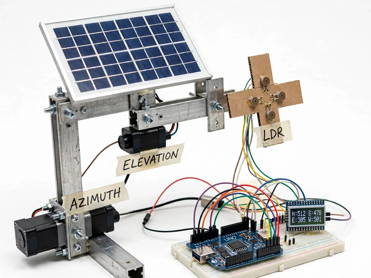
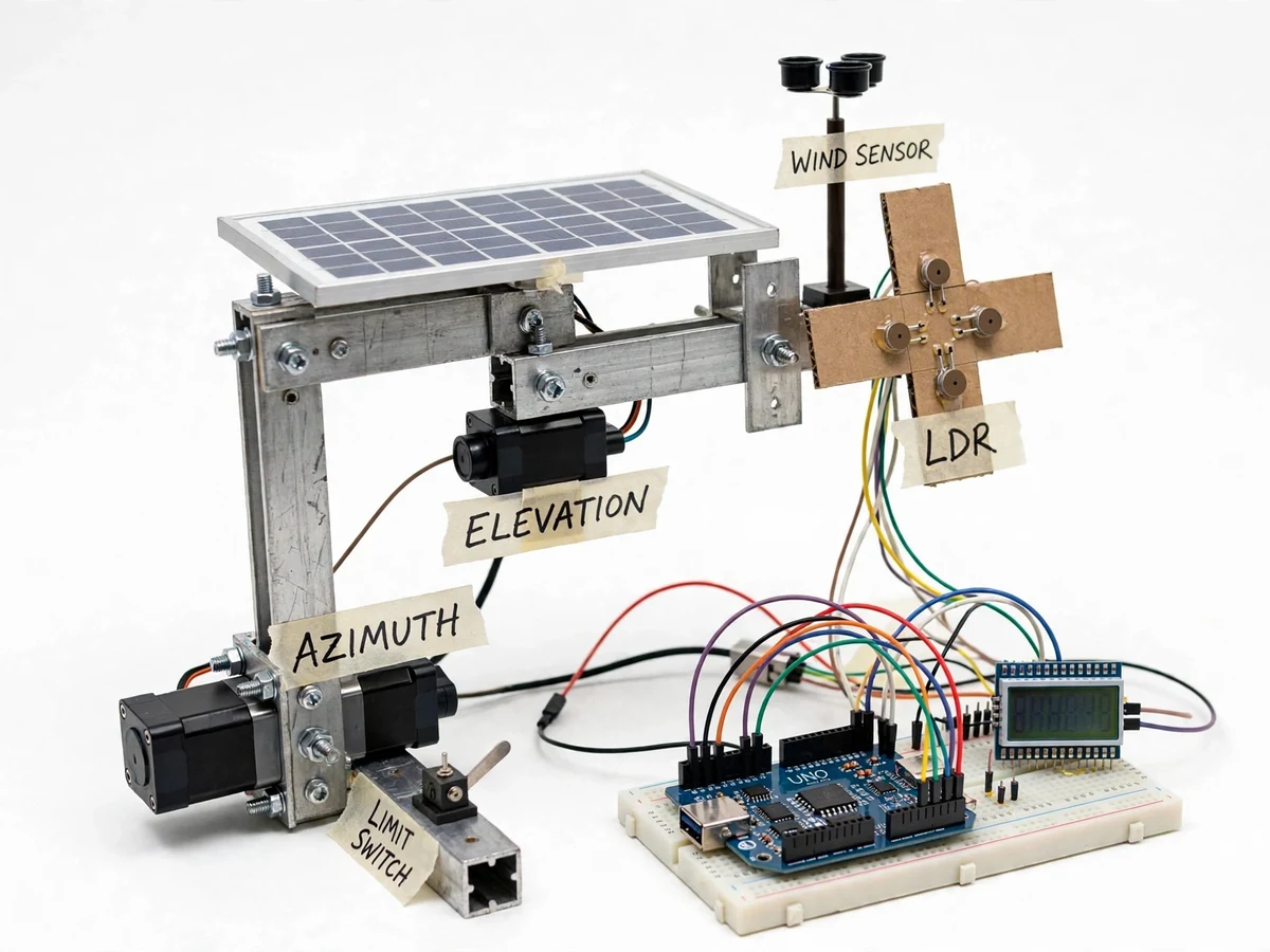
Four LDR sensors behind a cross divider sense light from each direction.
How it works
The dual-axis solar panel tracker works as a closed light-seeking loop with a safety override layered on top. Four LDR sensors sit in a quadrant pattern behind a small cross-shaped shade divider, so each sensor sees a slightly different amount of light depending on where the sun is. The Arduino reads all four sensors, compares the top pair against the bottom pair for elevation and the left pair against the right pair for azimuth, and drives the two servos in small steps toward the brighter side. When opposite pairs read nearly equal, the panel face is square to the sun and the tracker holds still. A dead-band stops the servos from hunting on tiny reading differences. Separately, a cup anemometer measures wind speed; above the configured threshold it drives the panel flat to its horizontal stow position, and tracking resumes only after a set calm period.
- The four LDR sensors, shaded by the cross divider, produce light readings that differ with the sun's position relative to the panel.
- The Arduino reads the four sensor voltages through its analog inputs, roughly once every 2 seconds (configurable).
- Top-versus-bottom readings are compared for elevation and left-versus-right for azimuth; the difference in each pair sets the correction direction.
- If a pair difference is larger than the dead-band, the matching servo steps a few degrees toward the brighter side; if both pairs are balanced, the panel holds position.
- Limit switches at each axis end stop the servos from driving past the mechanical travel limits.
- The cup anemometer continuously reports wind speed; above the configured threshold (8 m/s, configurable), the controller overrides tracking and drives the panel to its flat horizontal stow position.
- Tracking resumes only after wind speed has stayed below the threshold for a continuous calm period (approximately 60 seconds, configurable), so a single gust does not cause repeated stow-and-release cycling.
- The 16x2 LCD shows live LDR readings, wind speed and the current mode (Tracking, Stow or Manual), and the manual override switch lets the user position the panel by hand at any time.
Tech stack:
- Arduino Uno (ATmega328P)
- Arduino IDE (C/C++ firmware)
- LDR sensors (GL5528 type) with voltage-divider circuits
- MG996R servo motors
- Cup anemometer wind-speed sensor
- 16x2 LCD display
- Limit switches · manual override switch
- Aluminium angle frame · 10 W solar panel
| Parameter | Value |
|---|---|
| Controller | Arduino Uno (ATmega328P, 16 MHz clock, datasheet) |
| Light sensors | 4x LDR, GL5528 type (datasheet: approximately 10–20 kΩ at 10 lux, approximately 1 MΩ in darkness) |
| Tracking axes | 2 axes: azimuth and elevation |
| Azimuth range | Approximately 0–180° (design target, limited by frame and limit switches) |
| Elevation range | Approximately 0–90° (design target, flat stow at 0°) |
| Servo motors | 2x MG996R (datasheet: 9.4 kgf·cm stall torque at 4.8 V, 11 kgf·cm at 6 V, 0.17 s/60° at 4.8 V) |
| Panel | 10 W nominal polycrystalline panel (design target for the prototype build) |
| Wind sensor | Cup anemometer, pulse-output type |
| Wind-stow threshold | 8 m/s (configurable design target, set in firmware) |
| Calm period before resume | Approximately 60 seconds (configurable design target) |
| Sensor sampling interval | Approximately 2 seconds (configurable) |
| Display | 16x2 character LCD |
| Power supply | 12 V DC adapter for servos, 5 V regulated logic supply |
| Energy-gain claim | None measured — any tracking gain is stated as an expected benefit only, not a measured result |
Project features
The dual-axis solar panel tracker's strongest capabilities are its four-sensor differential light sensing, its two-axis servo positioning, its automatic wind-stow safety behaviour, and its readable LCD status display. Differential sensing is what makes the tracking robust: the controller compares sensor pairs rather than chasing an absolute brightness value, so it keeps working under hazy skies and changing daylight. Two-axis movement covers both the sun's daily east-west path and its seasonal height change, which a single-axis tracker cannot do. Wind-stow protection turns the prototype from a tracking demo into a protection system, and the LCD plus manual override make the whole control loop observable and demonstrable during a viva, which is exactly what a reviewer wants to see in a working hardware build, since every reading the LCD shows can be traced back to a sensor the student can point at.
- [Four-LDR quadrant sensing] Four LDR sensors behind a cross-shaped shade divider give top-bottom and left-right light comparisons, so the controller always knows which way to move without any clock, GPS or sun-position calculation.
- [Dual-axis servo tracking] Two MG996R servo motors drive the azimuth (left-right) and elevation (up-down) axes in small correction steps, holding the panel roughly square to the sun through the day.
- [Wind-stow protection] A cup anemometer feeds wind speed to the controller; above the configured threshold the panel is driven flat to its horizontal stow position, and tracking resumes only after a sustained calm period.
- [Dead-band anti-hunting logic] A configurable dead-band on each sensor-pair difference stops the servos from jittering on small reading noise, a behaviour students can demonstrate by shading one sensor by hand.
- [LCD status display] A 16x2 LCD shows the four LDR readings, wind speed and the current operating mode (Tracking, Stow or Manual), so the control loop is visible without a laptop.
- [Manual override and limit switches] A manual override switch parks or positions the panel by hand, and limit switches at each axis end prevent over-travel and mechanical damage.
- [Builder note — shading and hysteresis behaviour] During bench testing of this build, shading a single LDR by hand pulled the panel toward the brighter pair within a few correction steps, and without the dead-band the panel hunted visibly around the balance point; adding the dead-band and a short settle delay between steps stopped the hunting. This note is included in the report as a genuine build observation, not a measured performance claim.
What is included
- Working dual-axis solar tracker prototype (frame, panel, sensors, servos, controller wiring)
- Arduino firmware source code with commented tracking, dead-band and wind-stow logic
- Circuit diagram and wiring documentation
- Component list with part numbers and datasheet references
- Project report PDF (background, LDR sensing theory, control logic, wind-stow design, testing notes)
- PPT presentation for final review
- Viva Q&A preparation document (LDR characteristics, servo control, dead-band, wind loading)
Limitations & prerequisites
- LDR sensing follows the brightest light source, so it can be misled by strong artificial lights or bright reflections at night or indoors — it is a sun tracker, not a sun-position calculator.
- No measured energy-gain figure is claimed: the report states tracking benefit as an expected outcome only, since gain depends on location, season, panel size and weather.
- The prototype panel is a small 10 W nominal unit; the frame and servos are sized for that panel and are not rated for full-size rooftop panels.
- The 8 m/s wind-stow threshold is a configurable design target for the prototype, not a certified storm rating — the build is a bench and terrace demo, not a weatherproof installation.
- Servo positioning is open-loop in the sense that the controller infers position from sensor balance, not from an absolute angle encoder; backlash and servo dead-band limit pointing precision to a few degrees (approximate).
- The tracker needs an unobstructed view of the sky; nearby walls, trees or shade on any one sensor bias the quadrant comparison.
- Outdoor use needs weather protection for the electronics; the delivered prototype is built for demonstration, and the controller board is not supplied in a weatherproof enclosure.
Frequently Asked Questions
How does the tracker know where the sun is?
It does not calculate the sun's position at all. Four LDR sensors sit in quadrants behind a cross-shaped shade divider, and the Arduino compares opposite pairs: if the top pair reads brighter than the bottom pair, the panel tilts up, and likewise for left and right. When all four readings balance, the panel face is square to the brightest light, which outdoors is the sun. No clock, GPS or astronomical calculation is needed.
What happens when it gets windy?
The cup anemometer measures wind speed continuously, and when it crosses the configured threshold of 8 m/s the controller stops tracking and drives the panel flat to its horizontal stow position, where wind loading is lowest. Tracking resumes only after the wind has stayed below the threshold for about 60 seconds of calm, so a single gust does not cause repeated stow-and-release cycling. The threshold and calm period are both adjustable in the firmware.
Why does the panel sometimes stop moving even though the sun is out?
That is the dead-band doing its job: the controller only moves a servo when a sensor-pair difference exceeds a small threshold, so tiny reading noise from clouds, sensor drift or passing shade does not make the panel jitter back and forth. When the pairs are balanced within the dead-band, the panel is already pointed well enough and holding still saves servo wear and power. Students can demonstrate this by shading one LDR by hand and watching the panel correct in steps.
Can the wind threshold or the panel size be changed?
Yes, within limits: the stow threshold, calm period, sampling interval and dead-band are all constants in the firmware, so they can be adjusted for the demonstration site or a college's specific requirements without changing any of the hardware at all. A larger panel is possible only with a stronger frame and higher-torque servos, which would be a customised build rather than the standard prototype, since the MG996R servos and aluminium frame are sized for the 10 W panel.
Does it work on cloudy days or at night?
On cloudy days it still tracks, because the quadrant comparison works on relative brightness rather than absolute sunlight — the panel follows the brightest part of the sky, though the advantage over a fixed panel shrinks. At night the LDR readings fall to near-darkness, the pair differences collapse, and the tracker simply holds its last position until daylight returns; it does not consume meaningful servo power overnight.
Is this project suitable for a final-year project?
Yes, for Electrical, Electronics and related branches. It demonstrates analog sensing with LDR dividers, closed-loop servo control, dead-band and hysteresis design, wind-speed measurement, and a safety override — each of which can be explained, measured and questioned in a viva. The wind-stow behaviour also gives the report a second design problem beyond basic tracking.
Components & software requirements
- Arduino Uno (ATmega328P)
- Arduino IDE (C/C++ firmware)
- LDR sensors (GL5528 type) with voltage-divider circuits
- MG996R servo motors
- Cup anemometer wind-speed sensor
- 16x2 LCD display
- Limit switches · manual override switch
- Aluminium angle frame · 10 W solar panel
Delivery information
Built-to-order project. Delivery timeline is shared after order confirmation based on current queue.
Support terms
Complete documentation, setup guide, and viva preparation included. Support for setup and explanation provided.
Download free synopsis (PDF)
Enter your name and WhatsApp number — the synopsis PDF downloads immediately. We may send occasional project updates on WhatsApp; no spam.