
More project photos (2)
The problem
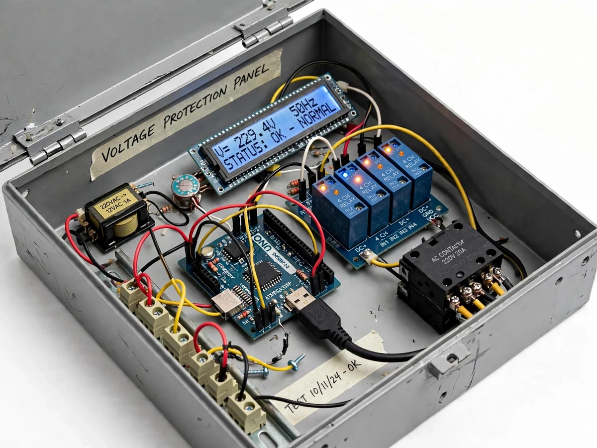
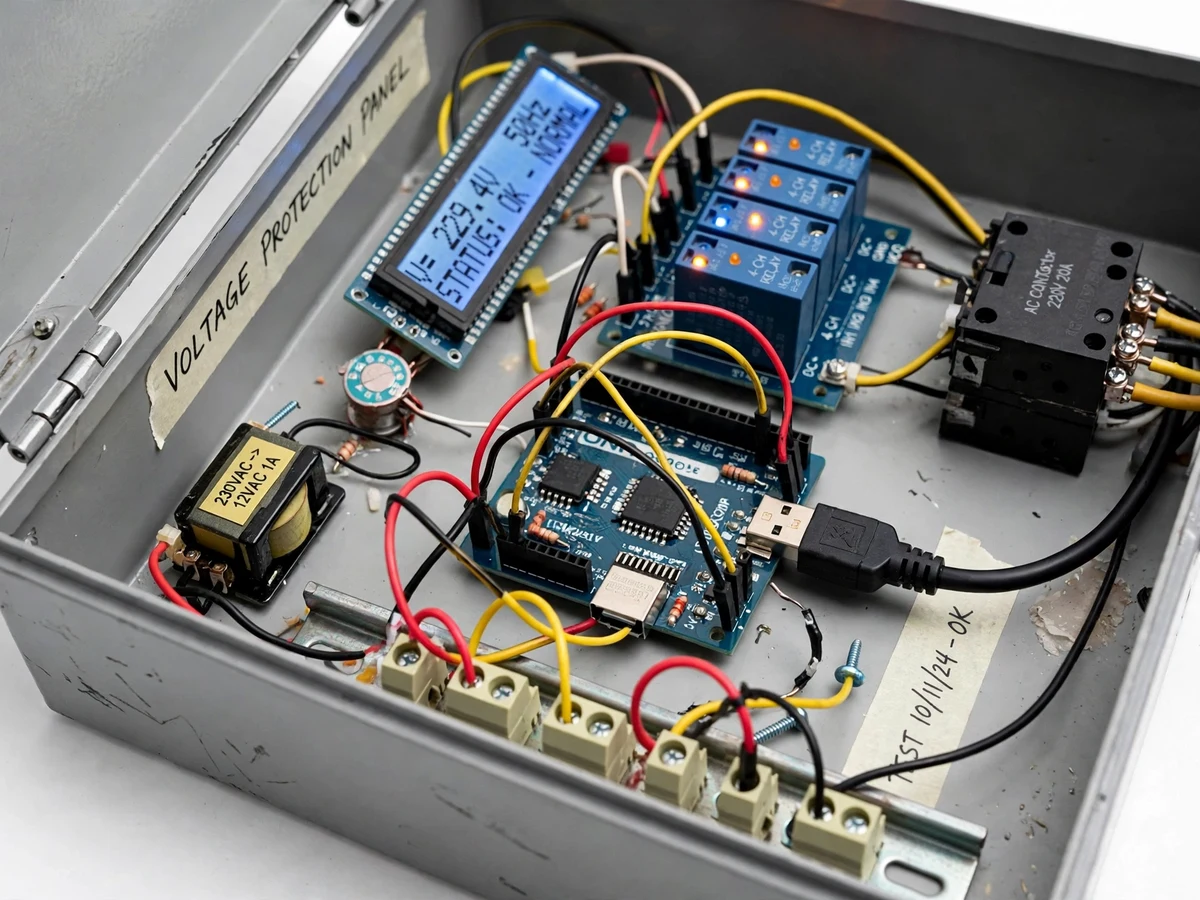
Single-phase loads such as pumps, refrigerators and workshop machines are damaged far more often by sustained under-voltage and over-voltage than by short circuits: motors overheat and stall when the voltage sags, while insulation and electronics fail when it surges. Yet in most college labs the protection chapter stays theoretical — students set thresholds on paper but never watch a sensing-to-trip chain act. This project closes that gap with a built, working protection panel. A small step-down transformer samples the mains, the conditioned signal is read by an Arduino, and firmware compares the measured RMS voltage against under and over thresholds set on the panel. On a confirmed out-of-range condition the trip relay drops the contactor and the load is disconnected; the LCD reports the fault type and the panel stays locked out until the operator resets it.
How it works
- The sensing transformer steps the 230 V mains down to a low-voltage AC sample, which is rectified, filtered and divided to the Arduino's 0–5 V ADC range.
- Firmware samples the conditioned signal, computes the RMS mains voltage, and displays it continuously on the 16x2 LCD.
- The measured voltage is compared every cycle against the under-voltage and over-voltage thresholds set on the panel.
- If the voltage stays outside the band for longer than the configured trip delay, the trip relay energizes and drops the contactor, disconnecting the test load.
- The LCD latches the fault type (UNDER VOLTAGE / OVER VOLTAGE), the buzzer sounds, and the panel refuses to re-arm.
- The operator inspects the fault, presses reset, and the contactor re-closes only if the voltage has returned inside the band.
- A buyer-run calibration procedure (comparing the LCD reading against a multimeter at several voltages) sets the sensing scale factor on the student's own build.
Tech stack:
- Arduino Uno (ATmega328P)
- Step-down sensing transformer + rectifier/filter/divider conditioning
- Relay module + single-phase contactor
- 16x2 character LCD
- Potentiometers / push-buttons for threshold setting
- Buzzer, reset and test push-buttons
- Arduino IDE (C/C++ firmware)
- Single-phase test load (lamp bank / small motor)
| Parameter | Value |
|---|---|
| Supply monitored | Single-phase 230 V AC nominal (design) |
| Sensing range | Approximately 0–300 V AC (design target) |
| Trip thresholds | Adjustable: under 160–210 V, over 240–280 V (design target) |
| Trip delay | 0.5–5 s, panel-adjustable (design target) |
| Voltage readout | LCD, resolution approximately 1 V (design target) |
| Trip chain | 5 V relay module driving contactor coil |
| Contactor rating | 230 V AC, 9 A utilization category AC-3 (datasheet, selected part) |
| Lockout | Manual reset only; auto re-close disabled |
| Response | Electromechanical trip in tens of ms after delay expiry (expected) |
Project features
- [True mains voltage sensing] A step-down sensing transformer with rectifier, filter and divider feeds a scaled DC signal to the Arduino ADC, and firmware converts it to an RMS voltage reading shown live on the LCD.
- [Adjustable under/over thresholds] Trip points are set with panel potentiometers (or push-buttons), so the student can demonstrate tripping at, say, 190 V low and 250 V high and explore the protection band.
- [Relay-contactor trip chain] A relay module drives a contactor that carries the actual load current, demonstrating how low-power control logic switches a power circuit — the same principle used in real protection panels.
- [Trip delay against nuisance tripping] A configurable 0.5–5 s confirmation delay means brief dips and switching transients do not trip the panel; only sustained out-of-range voltage does.
- [Manual-reset lockout] After a trip the contactor stays open and the LCD latches the fault type (UNDER / OVER) until the reset button is pressed, demonstrating protection lockout behaviour.
- [Live status display and alarm] The 16x2 LCD continuously shows measured voltage and NORMAL / TRIPPED status; a buzzer sounds on trip for classroom demonstrations.
- [Test mode for demos] A test push-button forces a simulated out-of-range reading so the trip chain can be demonstrated without disturbing the real mains supply.
What is included
- Wired under/over-voltage protection panel with contactor and LCD
- Arduino firmware with threshold, delay and lockout logic
- Wiring diagram and panel layout documentation
- Buyer-run voltage calibration procedure (multimeter comparison method)
- Project report PDF (protection theory, sensing design, methodology)
- PPT presentation for final review
- Viva Q&A preparation document (voltage sensing, relay logic, protection coordination basics)
Limitations & prerequisites
- Single-phase only — it does not monitor or protect three-phase supplies.
- This is a voltage-protection trainer, not a substitute for MCBs, fuses or short-circuit protection; it does not interrupt fault current.
- Trip thresholds and the voltage readout must be calibrated by the student against a multimeter; out-of-box readings are approximate.
- Electromechanical tripping takes tens of milliseconds after the delay expires — it is not a sub-cycle solid-state protection device.
- The contactor's 9 A rating limits the demo load; the panel must not be wired to loads beyond its rating.
- Sustained operation near the threshold band can cause repeated trip/reset cycling if the delay is set too short.
Frequently Asked Questions
How does the panel measure the mains voltage?
A small step-down transformer produces a low-voltage AC sample of the mains; it is rectified, filtered and divided to the Arduino ADC range, and firmware converts the reading to RMS volts shown on the LCD.
How are the trip thresholds set?
With panel potentiometers (or push-buttons) for the under and over points, so you can demonstrate, for example, a trip at 190 V sag and at 250 V swell during the viva.
Why is there a trip delay?
Real supplies have brief dips and switching transients. The 0.5–5 s confirmation delay ensures only sustained out-of-range voltage trips the panel, which is also how industrial under/over-voltage relays behave.
What happens after a trip?
The contactor drops the load, the LCD latches UNDER VOLTAGE or OVER VOLTAGE, the buzzer sounds, and nothing re-closes until you press reset — demonstrating protection lockout.
Can it protect against short circuits?
No. This panel protects against sustained voltage excursions only. Short-circuit and overload protection remain the job of MCBs and fuses, and the report states this boundary clearly.
Is this project suitable for a final-year project?
Yes — for Electrical and Electronics programs. It demonstrates voltage sensing, threshold protection logic, relay-contactor trip chains and lockout behaviour on a real wired panel. Suitable for B.E./B.Tech final-year projects in Electrical and Electronics engineering.
Components & software requirements
- Arduino Uno (ATmega328P)
- Step-down sensing transformer + rectifier/filter/divider conditioning
- Relay module + single-phase contactor
- 16x2 character LCD
- Potentiometers / push-buttons for threshold setting
- Buzzer, reset and test push-buttons
- Arduino IDE (C/C++ firmware)
- Single-phase test load (lamp bank / small motor)
Delivery information
Built-to-order project. Delivery timeline is shared after order confirmation based on current queue.
Support terms
Complete documentation, setup guide, and viva preparation included. Support for setup and explanation provided.