
More project photos (2)
The problem
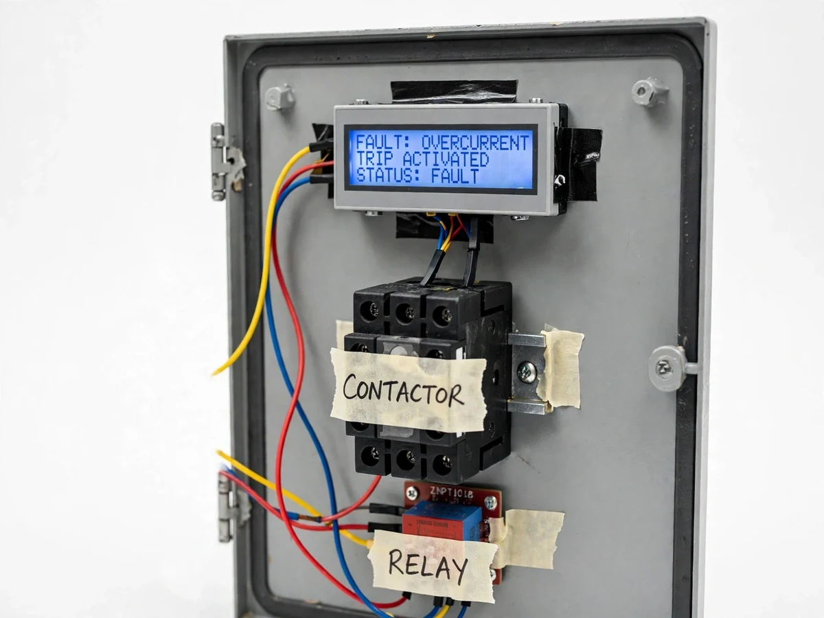
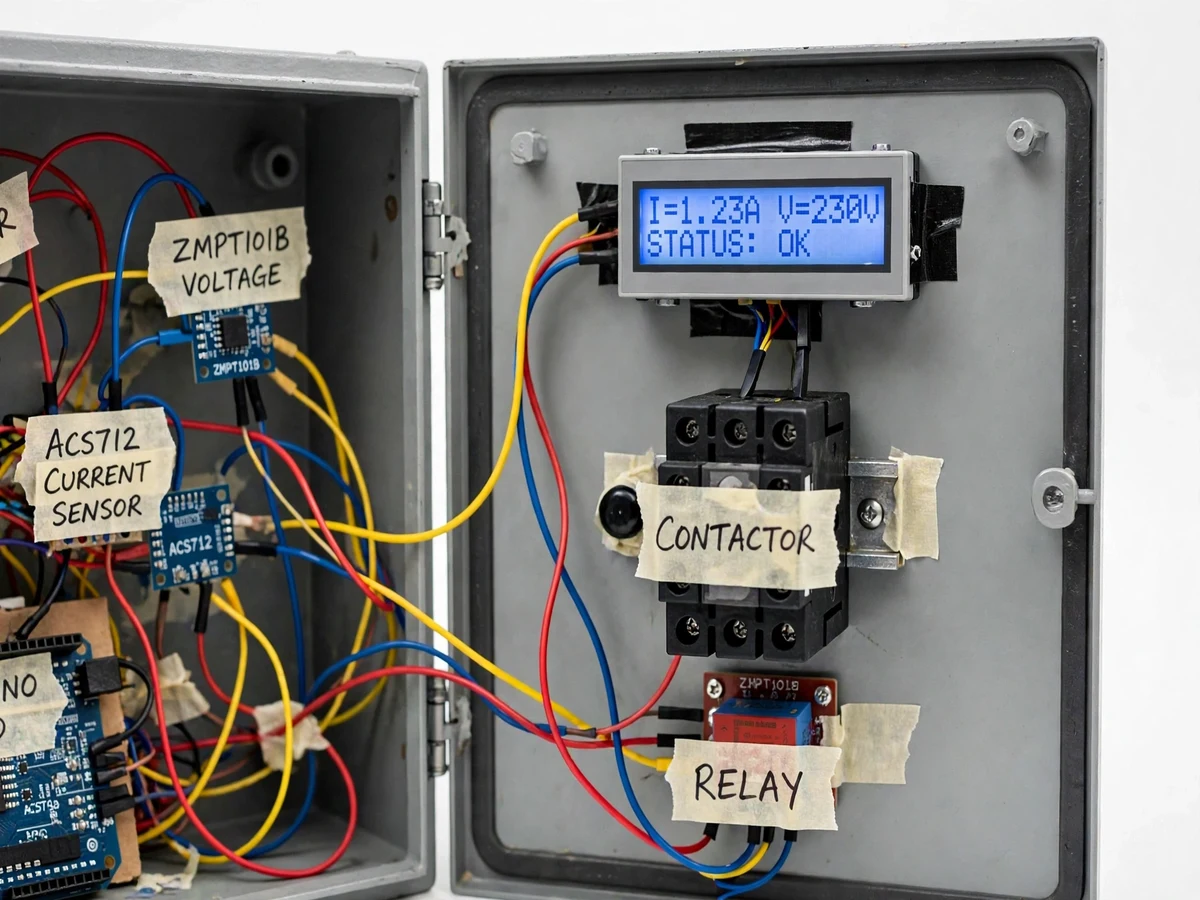
The Single-Phase Motor Protection Panel is a student-built control panel that protects single-phase motors and pumps - the workhorses of homes, farms and small workshops - from the electrical faults that destroy them. A submersible pump that runs dry because the borewell ran low keeps spinning with almost no load, drawing little current while its windings overheat; and a weak line that sags every evening starves the motor of voltage until insulation fails. Each failure looks ordinary from the outside - the motor simply stops one day - but the causes are measurable: too little current, too much current, or the wrong voltage. This panel watches all three through an ACS712 current sensor and a ZMPT101B voltage transformer, compares readings against user-set thresholds, and trips a contactor through an isolated relay when a fault outlasts its delay. Every trip latches and announces itself on a 16x2 LCD with a buzzer, needing a manual reset.
Protection panels are standard equipment in industry, but commercial motor-protection relays are sealed boxes a student cannot open or explain. This project rebuilds that logic from first principles with components a student can afford, wire and defend in a viva: a Hall-effect current sensor, a voltage transformer, a temperature sensor, a contactor, and a microcontroller running threshold-and-timer protection logic.
ACS712 current and ZMPT101B voltage sensors sample the motor line.
Follow the working sequence
How it works
The panel's loop runs sense, decide, trip. The ACS712 sits in series with the motor line and converts load current into a proportional voltage (185 mV per ampere, the datasheet value for the ACS712-05B); the ZMPT101B steps a sample of the 230 V mains down to a level the Arduino can read, and a DS18B20 reports winding-adjacent temperature. The Arduino samples these channels hundreds of times per second, computes true RMS current and average line voltage, and compares them against user-set thresholds: a dry-run current floor, an overload ceiling, and over/undervoltage limits. Each comparison runs through its own trip delay - the overload path uses an inverse-time-style count that tolerates the brief 5-7x inrush at switch-on, while dry-run and voltage faults trip after a few seconds of persistence. When any condition survives its delay, the firmware de-energizes the relay, the contactor drops out, the fault is named on the LCD with a buzzer tone, and the trip latches until reset.
- With the panel wired between the mains and the motor, a commissioning pass is run first: the motor is started healthy and the panel records its loaded RMS current as the reference baseline.
- In normal operation the ACS712 output is sampled several hundred times per second; the firmware computes true RMS current over each mains cycle and reads the ZMPT101B voltage sample and the DS18B20 temperature.
- RMS current is compared against the dry-run floor (a fraction of the commissioned baseline) and the overload ceiling (115 percent of the set current); voltage is compared against the user-set high and low limits.
- Any exceeded limit starts its own persistence timer: the overload path uses an inverse-time-style count long enough to ride through the 1-3 s switch-on inrush, while dry-run and voltage faults need a few seconds of continuous breach.
- When a timer completes, the firmware de-energizes the relay module, the contactor coil drops out and the motor circuit opens through the contactor contacts.
- The fault name (DRY RUN, OVERLOAD, OVER VOLT, UNDER VOLT, OVER TEMP) appears on the 16x2 LCD with a distinct buzzer tone, and the trip latches.
- The contactor stays open until the operator presses the reset push-button after clearing the fault; push-buttons also let the operator adjust thresholds without touching code.
Tech stack:
- Arduino Uno (ATmega328P)
- ACS712-05B Hall current sensor
- ZMPT101B voltage sensor module
- DS18B20 temperature sensor
- 230 V AC contactor · opto-isolated relay
- 16x2 LCD · piezo buzzer
- Embedded C firmware · Arduino IDE
- Plastic enclosure · panel wiring hardware
| Parameter | Value |
|---|---|
| Controller | Arduino Uno, ATmega328P, 10-bit ADC (datasheet value) |
| Current sensor | ACS712-05B: 185 mV/A sensitivity, 5 A range (datasheet values) |
| Voltage sensor | ZMPT101B transformer module for 230 V AC 50 Hz mains (design target) |
| Temperature sensor | DS18B20, ±0.5 °C accuracy, 1-Wire interface (datasheet value) |
| Power switching | 230 V AC coil contactor via opto-isolated relay module (design target) |
| Overload trip | Above 115% of set current for 8 s (design target) |
| Dry-run trip | Below 60% of commissioned baseline for 5 s (design target) |
| Voltage trip band | Approximately 180-260 V AC, user-configurable (design target) |
| Temperature alarm | Approximately 70 °C winding-adjacent, user-configurable (design target) |
| Display and alerts | 16 x 2 character LCD; piezo buzzer for fault tones |
| Logic supply | 5 V DC regulated; switched circuit 230 V AC (design target) |
| Trip behaviour | Latching; manual reset only |
| Certification | Demonstration panel - not a certified industrial protection relay |
Project features
The panel's four headline capabilities are dry-run tripping, overload tripping with inrush tolerance, over/undervoltage tripping, and latched fault annunciation. Dry-run protection is the rarest feature on student builds: the panel learns the motor's healthy loaded current during commissioning and trips when current falls below a configurable fraction of it - the exact signature of a pump moving no water. Overload protection watches for sustained overcurrent with an inverse-time-style delay, so genuine overloads trip while the few seconds of switch-on inrush pass through untouched. Voltage protection guards against the sagging rural supplies and occasional surges that burn out single-phase windings. Every trip latches, names itself on the 16x2 LCD and sounds the buzzer, and the contactor cannot reclose until the reset button is pressed - the behaviour of a real protection relay in a buildable student panel.
- [Dry-run trip (undercurrent protection)] The firmware records the motor's loaded current at commissioning and trips the contactor if running current stays below a configurable fraction of it - the signature of a pump running with no water. (Implemented)
- [Overload trip with inrush-aware delay] Overcurrent must persist through an inverse-time-style delay before the contactor trips, so the brief 5-7x starting inrush never causes nuisance tripping. (Implemented)
- [Over/undervoltage trip] The ZMPT101B line-voltage sample is compared against user-set high and low limits with a persistence delay; out-of-band voltage drops the contactor. (Implemented)
- [Winding temperature alarm] A DS18B20 mounted on the motor frame reports temperature continuously; crossing the set alarm point sounds the buzzer and can be configured to also trip the contactor. (Implemented; trip on temperature is configurable)
- [Contactor drive through isolated relay] The Arduino switches an optocoupler-isolated relay module that energizes the 230 V contactor coil, keeping mains completely separated from the 5 V control side. (Implemented)
- [Trip latching with manual reset] Any trip latches the contactor open and holds the fault name on the LCD until the reset push-button is pressed - no automatic restart into a live fault. (Implemented)
- [Fault annunciation: LCD plus buzzer] Live current, voltage and temperature show on the 16x2 LCD; each fault raises a distinct display message and buzzer tone. (Implemented)
- [Optional additions] GSM fault SMS, SD-card trip logging and a three-phase variant can be developed on request; they are not part of the base build. (Optional)
What is included
- Working protection panel prototype (enclosure, wired contactor, relay, sensors, LCD, buzzer)
- Arduino firmware source code with push-button threshold configuration
- Circuit and wiring diagram documentation
- Component list with sourcing notes
- ACS712 calibration procedure (zero-offset plus known-load scaling)
- Project report PDF (background, design, testing, safety)
- PPT presentation for final review
- Viva Q&A preparation document
Limitations & prerequisites
- Demonstration panel, not a certified industrial protection relay: mains wiring must follow local electrical codes and be checked by a qualified person before energizing.
- The ACS712-05B measures up to 5 A (design limit); motors drawing more need a higher-range sensor or a current-transformer variant, available as an extension.
- Trip timings (overload 8 s, dry-run 5 s) are design targets; they are verified against the actual motor during commissioning with the included procedure.
- The DS18B20 reads frame-adjacent temperature, not internal winding temperature; it is an early-warning alarm, not a winding-hotspot measurement.
- Voltage and current calibration depend on the builder's reference instruments (multimeter, clamp meter); readings carry the tolerance of the parts used.
- The panel switches a single-phase 230 V circuit only; it does not detect earth faults or provide insulation monitoring.
- Contactor and relay contacts wear with switching cycles; the design suits demonstration duty, not continuous industrial cycling.
Frequently Asked Questions
Is this project suitable for a final-year project?
Yes - for Electrical and Electronics engineering programs, and for IoT and Embedded students comfortable with a mains-adjacent build. The panel demonstrates sensor interfacing, true-RMS current measurement, threshold and timer-based protection logic, contactor driving and electrical safety practice, giving examiners several independent angles to question. It is a hardware build with visible, explainable behaviour, which suits a final-year demonstration.
How does dry-run detection actually work?
Dry-run is detected as sustained undercurrent. A pump moving water draws its normal loaded current; when the source runs dry, the impeller spins with almost no load and current falls sharply, typically to 30-50 percent of loaded current. During commissioning the panel records the motor's healthy loaded current and trips the contactor if running current stays below the set fraction (60 percent design target) for 5 s.
Why doesn't the overload trip false-trigger at switch-on?
Because the overload path uses an inrush-tolerant delay. A single-phase motor draws roughly 5-7 times its rated current for 1-3 s at switch-on while the rotor spins up - a normal event, not a fault. The overload trip only fires when current stays above 115 percent of the set point for 8 s (design targets), so the brief inrush clears the timer long before it completes.
Which controller is used and why?
An Arduino Uno (ATmega328P). Its 10-bit ADC has enough channels for current, voltage and temperature sampling at the rates RMS computation needs, its 5 V logic drives standard relay modules directly, and it is cheap, replaceable and present in nearly every college electronics lab. The firmware is written in Embedded C through the Arduino IDE, so students can read and explain every line.
How is the current sensor calibrated?
With a two-point procedure against a known load, included in the wiring documentation. First the panel records the ACS712 output with no motor connected to capture the zero-current offset; then a known resistive load - for example a 60 W incandescent bulb drawing approximately 0.26 A at 230 V - is connected and the reading is scaled to match. The slope is cross-checked against the datasheet value of 185 mV per ampere for the ACS712-05B.
Can this panel protect my home's submersible pump?
It is a demonstration and teaching panel, not certified protection equipment. It implements real protection logic - undercurrent, overcurrent, voltage and temperature trips - and it is honest about its limits: it has not undergone the type testing a certified motor-protection relay carries. Mains wiring must follow local electrical codes and be checked by a qualified person before the panel is energized.
Components & software requirements
- Arduino Uno (ATmega328P)
- ACS712-05B Hall current sensor
- ZMPT101B voltage sensor module
- DS18B20 temperature sensor
- 230 V AC contactor · opto-isolated relay
- 16x2 LCD · piezo buzzer
- Embedded C firmware · Arduino IDE
- Plastic enclosure · panel wiring hardware
Delivery information
Built-to-order project. Delivery timeline is shared after order confirmation based on current queue.
Support terms
Complete documentation, setup guide, and viva preparation included. Support for setup and explanation provided.
Download free synopsis (PDF)
Enter your name and WhatsApp number — the synopsis PDF downloads immediately. We may send occasional project updates on WhatsApp; no spam.