
More project photos (2)
The problem
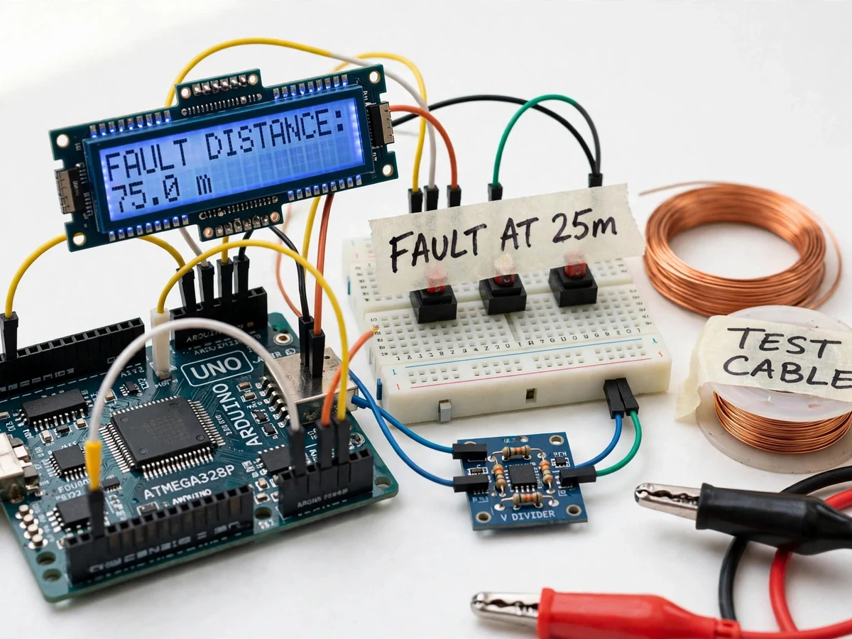
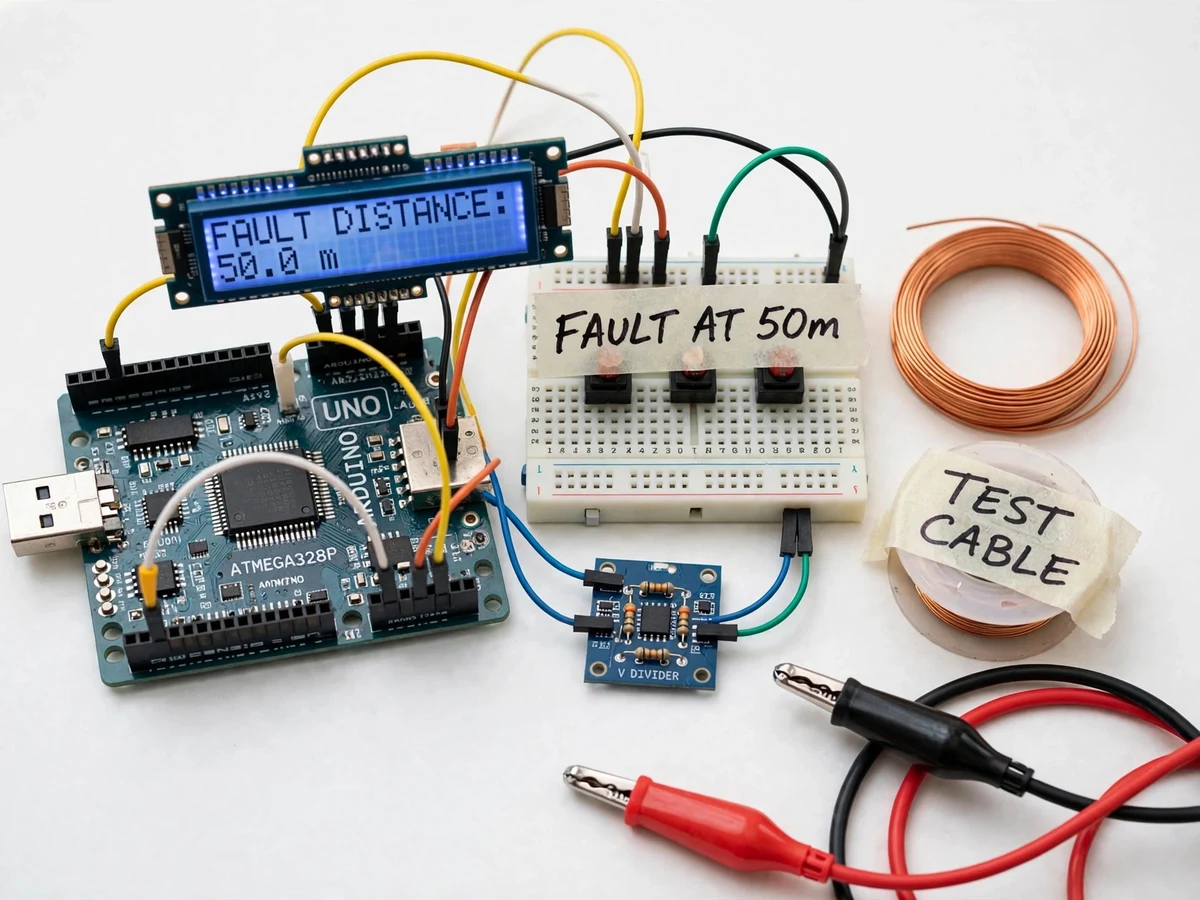
Locating a fault in an underground power cable is an expensive real-world problem: utilities must walk the cable route or dig trial pits to find the break point, because the cable itself cannot be seen or inspected. For a student build, that problem is scaled down to an honest demonstrator. This project builds an Arduino-based fault locator that works on a simulated underground cable — a spool of resistance wire of known resistance — and reports the fault distance in metres on a 16x2 LCD. The working principle is the same one behind classic fault-location theory: pass a known test current through the cable loop, measure the voltage drop across the faulted segment, and divide by the cable's calibrated per-metre resistance to get distance. Faults are created on demand with push buttons at marked points along the test cable, so every distance reading can be checked against a known fault position, and the student can demonstrate the measurement, the calibration and the limitations in the viva.
Presses fault buttons, reads the distance on the LCD, and runs the two-point calibration procedure.
Follow the working sequence
How it works
- The resistance-wire spool is connected as a test cable loop of known simulated length (approximately 100 m on the design build), and the regulated supply drives a constant low test current through it.
- A fault is simulated by pressing one of the fault push buttons, which shorts the test cable to ground at a marked point along the spool — a known, verifiable fault position.
- With the fault in place, the current path shortens to the fault point; the voltage-divider sensing board measures the voltage across the cable segment from the send end up to the fault.
- The Arduino reads the divided voltage on its 10-bit ADC, averages several samples to reduce noise, and reconstructs the voltage drop across the faulted segment.
- Using the per-metre resistance entered during the buyer's calibration run, the firmware computes fault distance = measured voltage drop ÷ (test current × resistance per metre).
- The result is shown in metres on the 16x2 LCD with the FAULT indicator active; pressing the reset button clears the simulated fault and the system re-arms for the next demonstration.
Tech stack:
- Arduino Uno
- 16x2 character LCD
- Resistance-wire test cable spool (simulated cable)
- Voltage-divider sensing board
- Push-button fault simulator
- Constant-current regulated supply
- 12V DC adapter
- Buzzer and fault LED
| Parameter | Value |
|---|---|
| Controller | Arduino Uno (ATmega328P), 10-bit ADC |
| Test cable | Resistance-wire spool, simulated length approximately 100 m (design target) |
| Fault simulation | Push-button shorts to ground at marked points, e.g. 25 m, 50 m, 75 m on the simulated cable |
| Test current | Low regulated DC current, approximately tens of milliamps (design target) |
| Sensing | Voltage-divider scaled to the 0–5 V ADC range, averaged samples |
| Display | 16x2 LCD: fault distance in metres, ADC reading, status line |
| Distance calculation | Distance = voltage drop ÷ (test current × calibrated resistance per metre) |
| Calibration | Two-point buyer-run procedure on the actual test cable; required before first use |
| Effective resolution | Limited by 10-bit ADC step size and analog noise; verified in the buyer's calibration run (design target, not a measured figure) |
| Power supply | 12V DC adapter; 5V logic for controller and LCD |
Project features
- [Voltage-drop fault sensing] A low constant test current is passed through the cable loop; the Arduino measures the voltage drop across the faulted segment through a scaled voltage-divider, converting it to fault distance from the calibrated per-metre resistance.
- [Simulated test cable loop] A spool of resistance wire of known, uniform resistance stands in for the buried underground cable, marked at simulated distances so faults have known positions to verify against.
- [Push-button fault simulation] Faults are created on demand with push buttons that short the test cable to ground at switchable marked points (for example 25 m, 50 m and 75 m on the simulated cable), making the demonstration repeatable and checkable.
- [LCD fault-distance readout] A 16x2 LCD shows the measured fault distance in metres, the raw ADC reading, and a CLEAR/FAULT status line so the student can see exactly what the firmware measured.
- [Regulated constant test current] The test current is held steady by a regulated source, because the distance calculation assumes the current is known and constant — a design detail the student can explain and defend in the viva.
- [Buyer-run calibration procedure] The per-metre resistance of the actual test cable is measured by the buyer in a two-point calibration run and entered into the firmware, so every distance figure traces back to a real measurement, not an assumed constant.
- [Fault alert indicator] A buzzer and LED signal when a fault is detected, distinguishing the fault state from the idle measurement state on the demonstrator.
What is included
- Working fault-locator prototype (Arduino, LCD, test cable spool, sensing board, fault simulator, indicators)
- Arduino firmware source code (ADC averaging, distance calculation, calibration storage, LCD driver)
- Wiring diagram and component connection notes
- Calibration procedure manual (two-point per-metre resistance measurement on the actual test cable)
- Complete bill of materials with specifications
- Fault-distance verification procedure (check each LCD reading against the marked fault points)
- Project report PDF (theory, design, methodology, calibration results template)
- PPT presentation for final review
- Viva Q&A preparation document (fault-location theory, voltage-drop method, ADC scaling, calibration)
Limitations & prerequisites
- This is a simulated-cable demonstrator: it does not locate faults in real buried cables, and no real-world underground accuracy or resolution figure is claimed — the buyer-run calibration only characterizes the test spool.
- Every distance reading is only as good as the calibration; drift in the test current or temperature changes in the resistance wire shift the per-metre resistance and the reading.
- The calculation assumes uniform wire resistance and a clean short to ground; a real fault with arcing or contact resistance would not read the same way — this is demonstrated theory, not field equipment.
- Faults can only be simulated at the fixed marked points on the spool; arbitrary continuous fault positions cannot be created in this build.
- Fine resolution is bounded by the 10-bit ADC step size and analog noise; small distance differences near the send end are the hardest to resolve.
- The demonstrator works on low-voltage test current only; it must never be connected to mains or any live power cable.
Frequently Asked Questions
How does the voltage-drop method find the fault distance?
A known constant current is passed through the test cable loop. When a fault shorts the cable to ground, the current path shortens to that point, so the voltage drop across the segment up to the fault is proportional to its length. The Arduino measures that drop, and the firmware divides it by the product of test current and the cable's calibrated per-metre resistance to display the distance in metres.
Is this tested on a real underground cable?
No. The demonstrator uses a resistance-wire spool that simulates a buried cable with known, uniform resistance, and faults are created with push buttons at marked points. This keeps the project buildable and verifiable in a college lab. It demonstrates the same measurement principle used in real fault-location theory, but it does not claim real-world underground locating ability.
Why is calibration needed?
The distance formula needs the cable's per-metre resistance, which differs between spools and drifts with temperature. The included two-point procedure has the buyer measure the actual spool and store the value in firmware. Any reading taken before calibration is based on an assumed constant and should not be trusted.
What power supply does it need?
A 12V DC adapter feeds the unit; an onboard regulator supplies the 5V logic for the Arduino and LCD, and the test current source is regulated from the same input. No batteries are needed, and nothing in the build touches mains voltage.
Can it show faults at any distance?
Only at the marked simulation points on the spool (for example 25 m, 50 m and 75 m on the design build). Continuous fault positioning would need a sliding contact on the wire, which can be discussed as a future extension but is not part of this build.
Is this project suitable for a final-year project?
Yes — for Electrical Engineering programs. It demonstrates power-system fault-location theory, analog sensing with voltage dividers, ADC scaling and averaging, calibration practice and embedded firmware, all verifiable against known fault positions. Suitable for B.E./B.Tech final-year projects in Electrical Engineering.
Components & software requirements
- Arduino Uno
- 16x2 character LCD
- Resistance-wire test cable spool (simulated cable)
- Voltage-divider sensing board
- Push-button fault simulator
- Constant-current regulated supply
- 12V DC adapter
- Buzzer and fault LED
Delivery information
Built-to-order project. Delivery timeline is shared after order confirmation based on current queue.
Support terms
Complete documentation, setup guide, and viva preparation included. Support for setup and explanation provided.
Download free synopsis (PDF)
Enter your name and email — the synopsis PDF downloads immediately. We may send occasional project updates; no spam, unsubscribe anytime.