
More project photos (2)
The problem
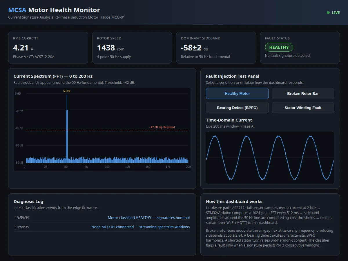
Induction motors fail gradually — a cracked rotor bar, a pitted bearing or a shorted stator turn all leave traces in the motor's current long before the machine stops. Motor Current Signature Analysis (MCSA) reads those traces without vibration sensors or dismantling: faults modulate the air-gap flux and produce characteristic frequency sidebands around the supply frequency in the stator current spectrum. This project turns that industrial technique into a buildable student prototype. A Hall-effect current sensor samples the motor current, the microcontroller computes a real-time FFT, and a web dashboard shows the live spectrum, the time-domain waveform, key KPIs and a diagnosis log that flags developing faults. It is a rare combination of power engineering, embedded systems and signal processing in one project.
How it works
- The ACS712 Hall-effect sensor in series with the motor phase produces a voltage proportional to the instantaneous current, biased to mid-rail for the ADC.
- The microcontroller samples the sensor at approximately 2 kHz through an anti-alias RC filter.
- Each 512 ms window is Hanning-windowed and transformed with a 1024-point FFT (design target) to produce the current spectrum.
- The 50 Hz fundamental is located; sideband amplitudes at the rotor-bar (50 ± 2·s·f), bearing (BPFO) and 3rd-harmonic frequencies are extracted.
- A rule-based classifier flags a fault only when a signature exceeds its threshold for three consecutive windows, suppressing transient false alarms.
- Spectrum frames and fault status are published over Wi-Fi (MQTT); the dashboard renders the spectrum, KPIs, event log and the local 16x2 LCD mirrors RMS current and status.
Tech stack:
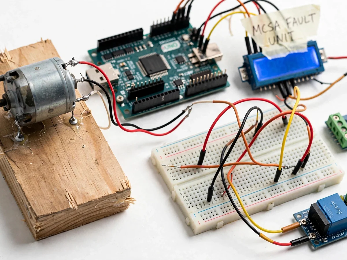
- Arduino Uno / STM32 (edge acquisition & FFT)
- ACS712-20A Hall current sensor
- 16x2 LCD (local status display)
- MQTT over Wi-Fi (spectrum streaming)
- HTML/CSS/JS live dashboard
- 12 V DC / small single-phase motor (test load)
| Parameter | Value |
|---|---|
| Current sensor | ACS712-20A Hall-effect (datasheet: 100 mV/A) |
| Sampling rate | Approximately 2 kHz (design target) |
| FFT size | 1024 points, Hanning window (design target) |
| Spectrum refresh | Approximately every 512 ms (expected) |
| Frequency range | 0–200 Hz displayed |
| Fault trip threshold | −42 dB relative to fundamental (configurable) |
| Classifier persistence | 3 consecutive windows (design) |
| Dashboard link | Wi-Fi MQTT, browser-based, no install |
| Test motor | 12 V DC or small single-phase induction motor |
Project features
- [Live FFT spectrum dashboard] The current spectrum from 0–200 Hz renders in real time with the 50 Hz fundamental marked and a configurable trip threshold line — fault sidebands are visible the moment they cross it.
- [Broken-rotor-bar detection] Sidebands at 50 ± 2·s·f are extracted and compared against the threshold, with the classifier requiring the signature to persist across three consecutive windows before flagging.
- [Bearing-defect monitoring] Characteristic BPFO harmonics are tracked in the spectrum, giving an early, quantified warning of bearing damage instead of a post-failure discovery.
- [Stator-winding fault indication] Elevated 3rd-harmonic content and phase-imbalance signatures are reported with a plain-language diagnosis on the dashboard.
- [Fault-injection test panel] Select healthy, rotor, bearing or stator conditions in the demo to show exactly how each signature appears in the spectrum — ideal for the viva demonstration.
- [Time-domain current view] A live 200 ms window of the phase current runs alongside the spectrum, so the link between waveform distortion and spectral content is visible.
- [Diagnosis event log] Every classification with timestamp is logged on the dashboard, producing ready-made evidence for the project report.
What is included
- Complete sensing prototype (sensor, controller, LCD, wiring)
- Edge firmware (ADC sampling, FFT, classifier, MQTT publishing)
- Live web dashboard (spectrum, time-domain view, KPIs, event log, fault-injection panel)
- Wiring diagram and calibration procedure
- Project report PDF (MCSA theory, signal path, methodology, results)
- PPT presentation for final review
- Viva Q&A preparation document (FFT, sidebands, slip, classifier design)
Limitations & prerequisites
- Demonstrates MCSA on a single phase of a small test motor — a full three-phase industrial deployment would need three sensors and Park-vector analysis.
- Fault signatures are shown with injected/test conditions on the lab rig; the build does not claim detection rates measured on industrial motors.
- −42 dB threshold and 1024-point FFT are design targets for the delivered firmware, stated honestly and adjustable in code.
- Classification is rule-based, not machine-learned — it detects known signatures, not unknown fault types.
- The prototype monitors; it does not trip the motor — protective tripping is listed as future scope.
Frequently Asked Questions
What is Motor Current Signature Analysis?
MCSA is a non-invasive diagnostic method: mechanical and electrical faults in an induction motor modulate its magnetic field, which shows up as extra frequency components (sidebands) in the stator current. Analyzing the current spectrum reveals faults like broken rotor bars or bearing damage without vibration sensors or opening the machine.
Which faults does this project detect?
Three classic signatures: broken rotor bars (sidebands at 50 ± 2·s·f around the supply frequency), bearing defects (BPFO harmonics), and stator winding faults (elevated 3rd-harmonic content with phase imbalance). Each is flagged on the dashboard with a plain-language diagnosis.
How does the dashboard get the spectrum?
The microcontroller computes the FFT on the edge device and publishes spectrum frames over Wi-Fi using MQTT. The browser dashboard subscribes and renders the live plot — no software install needed, it runs on any laptop or phone on the same network.
Why does the classifier need three consecutive windows?
A single FFT window can show a transient spike from a load change or switching noise. Requiring the signature to persist across three windows (about 1.5 seconds) suppresses false alarms while still responding quickly to real faults.
Can it protect the motor automatically?
As delivered it monitors and alarms; it does not trip the contactor. Adding an automatic protective trip on a confirmed fault is documented as future scope in the report.
Is this project suitable for a final-year project?
Yes — for Electrical and Electronics programs. It combines power engineering, embedded systems, digital signal processing and a real dashboard, and every stage is explainable in a viva. Suitable for B.E./B.Tech final-year projects in Electrical and Electronics Engineering.
Components & software requirements
- Arduino Uno / STM32 (edge acquisition & FFT)
- ACS712-20A Hall current sensor
- 16x2 LCD (local status display)
- MQTT over Wi-Fi (spectrum streaming)
- HTML/CSS/JS live dashboard
- 12 V DC / small single-phase motor (test load)
Delivery information
Built-to-order project. Delivery timeline is shared after order confirmation based on current queue.
Support terms
Complete documentation, setup guide, and viva preparation included. Support for setup and explanation provided.