
More project photos (2)
The problem
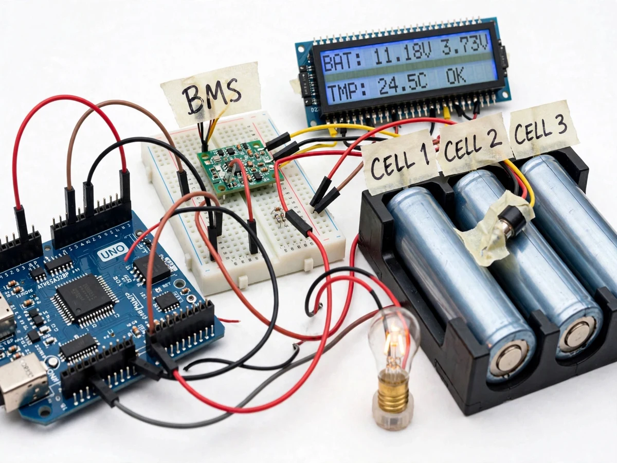
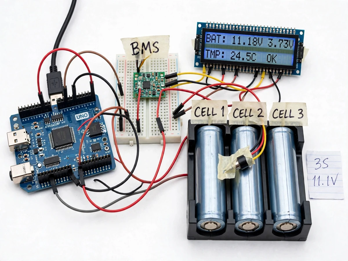
A battery management system (BMS) for a lithium-ion battery pack is the circuit that watches every cell in the pack and disconnects the charger or the load before any single cell is damaged. This project builds that system for a 3S pack of three 18650 cells using an Arduino Uno: three voltage-divider taps feed each cell voltage to the Arduino, an ACS712 sensor measures pack current, and a DS18B20 sensor measures cell temperature. The Arduino compares every reading with safe limits, switches on a bleed resistor to balance any cell that runs high, and opens a MOSFET switch to cut off charging above 4.25 V per cell or discharge below 3.00 V per cell. A 16x2 LCD shows cell voltages, current, temperature and state of charge, with a 3S protection board as hardware backup. The build is an educational prototype, not a certified or vehicle-grade BMS, demonstrated with a 12 V DC bulb as the load.
Lithium-ion cells are unforgiving: a single cell charged past 4.2 V or drained below about 3.0 V loses capacity permanently, and in the worst case overheats. In a series pack the risk is worse, because cells never age identically — one cell reaches full charge while the others are still catching up, so charging by pack voltage alone quietly overcharges the strongest cell every cycle. Most student battery projects ignore this entirely and connect cells straight to a charger and a load. This project closes that gap with a working monitor-and-protect loop the student can demonstrate live: force one cell high or low and watch the system cut off, balance, and report. It pairs naturally with a solar charge controller project, a home inverter or UPS build, and an e-bike battery pack project.
A battery management system does not charge the battery — it watches every cell and opens a switch the instant any single cell leaves its safe window. Builder note: each divider tap is sized so the voltage at the Arduino pin never exceeds 5 V, because the top tap of a 3S pack reaches 12.6 V at full charge, and a raw tap wired straight to an analog pin would destroy that input.
Three 18650 cells in series: 11.1 V nominal, 12.6 V at full charge.
Follow the working sequence
How it works
A battery management system works as a continuous sense-decide-protect loop, and this build runs that loop once every second. It starts by sensing: three voltage-divider taps bring each cell voltage down into the Arduino's 0–5 V analog range, the ACS712 sensor reports pack current, and the DS18B20 reports cell temperature. The Arduino then decides: it compares each cell against the over-charge limit of 4.25 V and the over-discharge limit of 3.00 V, compares current against 3 A, and temperature against 45 °C, while updating the state-of-charge estimate from the integrated current. Finally it protects: if a cell is high during charging, its balance resistor switches on; if any limit is crossed, the charge or load MOSFET opens and the LCD names the fault. A 3S protection board wired in series provides a second, hardware-only cut-off if the Arduino ever fails to act.
- Three 18650 cells in series form the 3S pack (11.1 V nominal, 12.6 V at full charge), with a tap wired from the top of each cell into its own voltage divider.
- Each divider scales its tap below 5 V and feeds one Arduino analog pin (A0–A2); the 10-bit ADC converts each reading at approximately 4.9 mV per step (datasheet value).
- The ACS712-05B current sensor measures pack current at 185 mV/A sensitivity (datasheet value), and the DS18B20 measures cell temperature on a single digital pin.
- Every second the firmware computes the three cell voltages, pack voltage, current, temperature and state of charge, and refreshes the 16x2 LCD and serial log.
- During charging, any cell above its neighbours has its bleed resistor switched on by a MOSFET, draining approximately 100 mA (design target) until the cells match.
- If any cell exceeds 4.25 V (design target), the charge MOSFET opens and charging stops; if any cell drops below 3.00 V (design target), the load MOSFET opens and the load is disconnected.
- If current exceeds 3 A or temperature exceeds 45 °C (design targets), the load is disconnected and the LCD shows the fault; the 3S protection board provides an independent hardware backup cut-off.
Comparing battery protection approaches
| Approach | What it protects | What it cannot do |
|---|---|---|
| Bare pack, no protection | Nothing — cells are directly exposed | No cut-off, no balancing, no warning of any kind |
| TP4056 + DW01 single-cell module | One cell: CC/CV charging to 4.2 V, over-charge at 4.3 V and over-discharge at 2.4 V (datasheet values) | Single cell only — it cannot manage a 3S series pack or balance cells |
| This Arduino BMS (3S) | Each of 3 cells: monitoring, passive balancing, over-charge, over-discharge, over-current and thermal cut-offs | Educational prototype — not certified or vehicle-grade, and balancing is passive, not active |
Tech stack:
- Arduino Uno (ATmega328P)
- Arduino IDE (C/C++ firmware)
- 18650 lithium-ion cells (3S pack)
- ACS712-05B current sensor
- DS18B20 temperature sensor
- 16x2 LCD with I2C backpack
- N-channel MOSFETs · bleed resistors
- 3S protection board (HX-3S class)
| Parameter | Value |
|---|---|
| Pack configuration | 3 cells in series (3S) |
| Cell type | 18650 lithium-ion, 3.7 V nominal per cell (datasheet value) |
| Pack voltage | 11.1 V nominal, 12.6 V at full charge (datasheet-derived: 3 × 4.2 V) |
| Cell capacity | 2600 mAh per cell (datasheet value, cell-dependent) |
| Controller | Arduino Uno, ATmega328P, 16 MHz clock speed |
| ADC resolution | 10-bit, 6 analog inputs, approximately 4.9 mV per step at 5 V reference (datasheet value) |
| Over-charge cut-off | 4.25 V per cell (design target) |
| Over-discharge cut-off | 3.00 V per cell (design target) |
| Over-current cut-off | 3 A (design target) |
| Thermal cut-off | 45 °C (design target) |
| Balance bleed current | Approximately 100 mA per cell (design target) |
| Current sensor | ACS712-05B, ±5 A range, 185 mV/A sensitivity (datasheet value) |
| Temperature sensor | DS18B20, ±0.5 °C accuracy from −10 °C to +85 °C (datasheet value) |
| Display | 16x2 character LCD with I2C backpack |
| Charge input | 12.6 V DC adapter (design target) |
| Demo load | 12 V DC bulb (design target) |
| Sensing interval | 1 reading per second (design target) |
Project features
A battery management system for a lithium-ion pack stands or falls on four capabilities, and this build implements all four. First, per-cell voltage monitoring: each of the three 18650 cells is measured individually through its own divider tap, so an unbalanced cell is visible instead of hidden inside the pack voltage. Second, passive cell balancing: a MOSFET-switched bleed resistor drains any cell that runs above its neighbours during charging. Third, three independent cut-offs: over-charge, over-discharge and over-current each open a MOSFET switch to disconnect the charger or the load. Fourth, state-of-charge estimation: the firmware combines coulomb counting from the current sensor with a voltage lookup, and shows the result live on the LCD. Temperature and current complete the picture: the DS18B20 watches cell temperature and the ACS712 watches pack current, so a hot cell or a heavy load triggers the same protective cut-off as a bad voltage.
- [Per-cell voltage monitoring] Three divider taps feed each 18650 cell voltage to separate Arduino analog pins, so the firmware sees every cell individually instead of only the 11.1 V pack total.
- [Passive cell balancing] A MOSFET-switched bleed resistor across each cell drains a high cell at approximately 100 mA (design target) during charging, pulling the three cells back toward the same voltage.
- [Over-charge cut-off] When any cell crosses 4.25 V (design target), the charge MOSFET opens and charging stops, with the LCD flagging which cell tripped.
- [Over-discharge cut-off] When any cell falls below 3.00 V (design target), the load MOSFET opens and the pack is disconnected from the load before deep discharge can damage a cell.
- [Over-current and short-circuit cut-off] An ACS712-05B Hall-effect current sensor watches pack current, and the firmware opens the load switch above 3 A (design target).
- [Temperature monitoring with thermal cut-off] A DS18B20 sensor taped to a cell reports temperature to ±0.5 °C (datasheet value, −10 °C to +85 °C), and charging and discharge stop above 45 °C (design target).
- [State-of-charge estimation and display] The firmware integrates pack current over time (coulomb counting) and cross-checks it against an open-circuit-voltage lookup table, showing SOC, cell voltages, current and temperature on a 16x2 LCD and the serial monitor.
What is included
- Working 3S lithium-ion BMS prototype (Arduino Uno, 3-cell 18650 holder, BMS board, LCD, sensors, MOSFET cut-off stage)
- Complete Arduino firmware with per-cell monitoring, balancing, cut-offs, SOC estimation and LCD/serial display
- Circuit diagram and wiring documentation, including divider sizing and the calibration procedure
- Project report PDF (background, BMS theory, methodology, results, safety notes)
- PPT presentation for final review
- Viva Q&A preparation document (cell chemistry, balancing, cut-off logic, SOC methods, safety limits)
- Demonstration guide: how to show balancing, over-charge cut-off and over-discharge cut-off live
Limitations & prerequisites
- Educational prototype only — not a certified, automotive or vehicle-grade BMS, and not a substitute for a commercial BMS in any real product.
- Passive balancing only: bleed resistors drain high cells slowly (approximately 100 mA, design target) and waste the energy as heat; active balancing is not implemented.
- SOC is an estimate from coulomb counting plus a voltage lookup, not a laboratory measurement; it drifts over time and needs a full-charge reset to stay honest.
- Voltage readings depend on divider resistor tolerance and calibration; the buyer-run calibration procedure must be followed before trusting the displayed voltages.
- The demo load is a 12 V DC bulb (design target); the prototype is not rated for high-current loads such as motors or inverters.
- Lithium-ion cells must be matched (same model, capacity and age) — mixing old and new cells defeats balancing and is not supported.
- Never charge the pack unattended, and never use damaged, swollen or unprotected cells; the prototype includes a fuse and a hardware protection board, but safe handling is still the user's responsibility.
Frequently Asked Questions
Which controller is used and why an Arduino Uno?
The Arduino Uno (ATmega328P) is used because its 6 analog inputs and 10-bit ADC cover the three cell-voltage taps, the current sensor and spare inputs in one board, and its 5 V logic matches the LCD and sensors directly without extra level shifting. It is also the controller most examiners expect students to explain confidently.
How does passive cell balancing work?
During charging, the firmware compares the three cell voltages and switches on a bleed resistor across any cell that runs above its neighbours, draining approximately 100 mA (design target) from that cell until the voltages match, so the pack finishes charging with all three cells at the same voltage. It is slow and wastes a little energy as heat, which is why it is called passive balancing.
Can I charge the 3S pack with a TP4056 module?
No — the TP4056 is a single-cell charger IC with a fixed 4.2 V output (datasheet value), so it cannot charge three cells in series or balance them; this build charges from a 12.6 V DC adapter through the Arduino-controlled charge MOSFET instead. A TP4056 module is the right charger for one cell, not for a 3S pack.
What happens if one cell goes over voltage during charging?
The firmware detects it within one sensing cycle (1 second, design target), opens the charge MOSFET to stop charging, switches on that cell's balance resistor, and shows which cell tripped on the LCD, while the 3S protection board behind it provides an independent hardware cut-off if the Arduino ever fails to act.
How is the state of charge estimated?
The firmware integrates pack current over time (coulomb counting) from the ACS712 sensor and cross-checks the result against an open-circuit-voltage lookup table for lithium-ion cells, resetting the estimate at full charge to limit drift so the LCD percentage stays honest across cycles. It is an estimate, not a measured capacity.
Is this project suitable for a final-year project?
Yes — for Electrical, Electronics and IoT & Embedded programs, because it demonstrates power electronics, embedded sensing, protection logic and battery chemistry in one working prototype, and the live cut-off and balancing demos give strong material for the viva and the final demonstration. Request a quotation on WhatsApp with your branch, deadline and any custom scope, and the price and delivery timeline are confirmed before the build starts.
Components & software requirements
- Arduino Uno (ATmega328P)
- Arduino IDE (C/C++ firmware)
- 18650 lithium-ion cells (3S pack)
- ACS712-05B current sensor
- DS18B20 temperature sensor
- 16x2 LCD with I2C backpack
- N-channel MOSFETs · bleed resistors
- 3S protection board (HX-3S class)
Delivery information
Built-to-order project. Delivery timeline is shared after order confirmation based on current queue.
Support terms
Complete documentation, setup guide, and viva preparation included. Support for setup and explanation provided.
Download free synopsis (PDF)
Enter your name and WhatsApp number — the synopsis PDF downloads immediately. We may send occasional project updates on WhatsApp; no spam.