
More project photos (2)
The problem
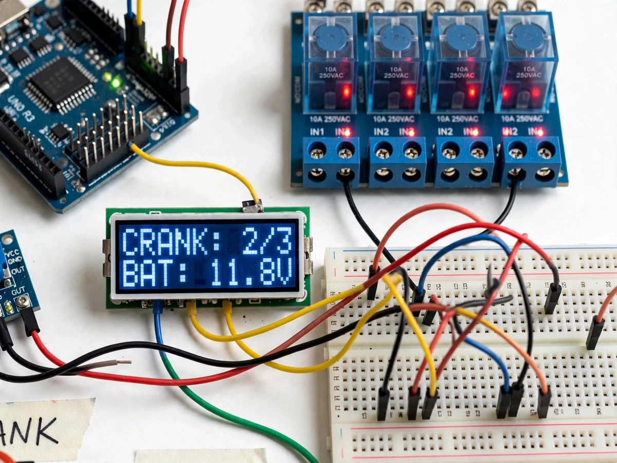
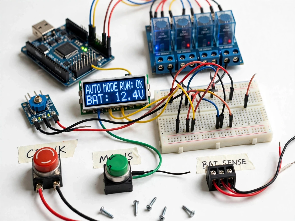
Standby generators usually sit idle until someone notices a power cut, walks to the set, and cranks it manually. That delay is acceptable for a demo lab but not for the use case these sets exist for, and the cranking itself is rough on the starter motor and battery when done blindly: over-cranking overheats the starter, repeated attempts drain a weak battery, and transferring load to an engine that has not stabilized can stall it. Commercial automatic mains failure (AMF) panels use timed start logic, but they are sealed units a student cannot tune. This project fills that teaching gap with an Arduino-based auto-start controller that senses mains failure, measures battery voltage through a divider sensing stage, executes a timed crank sequence with rest intervals and a limited number of attempts, confirms the engine run, and manages warmup and cooldown before and after load transfer. The design targets mirror real AMF panels (a few timed crank attempts, rest between tries, run confirmation, lockout on failure), so the student learns the protection-and-sequencing thinking behind automatic start systems, not just relay wiring.
AC-coil relay that stays energized while mains supply is present; its contact opening tells the controller the supply has failed.
Follow the working sequence
How it works
- The mains-sense relay stays energized while AC supply is present; when the supply fails, its contact opens and the Arduino detects the change, starting a start-delay timer (design target 5 s) to ride out momentary dips.
- Before cranking, firmware reads the battery voltage through the 0–25 V divider into the 10-bit ADC; if the voltage is below the low-battery threshold (design target 11.0 V), cranking is inhibited and the LCD shows the battery fault.
- The controller energizes the crank relay for the configured crank duration (design target 5 s), then releases it for a rest interval (design target 10 s) while watching for the engine-run feedback signal.
- If no run is confirmed, the sequence repeats up to the attempt limit (design target 3 attempts); after the last failed attempt the controller locks out, raises "fail to start" on the LCD, and requires a manual reset.
- Once the run is confirmed, the engine runs unloaded through a warmup delay (design target 30 s), after which the load-transfer relay closes and the load moves to the generator.
- When mains returns and stays healthy for a confirmation delay (design target 60 s), the load transfers back to mains, the engine runs through a cooldown period (design target 60 s), and the controller returns to standby.
Tech stack:
- Arduino Uno (ATmega328P) · 5 V logic
- Voltage-sensor module (divider-based, 0–25 V input)
- 4-channel relay module (optoisolated, 5 V)
- 16x2 character LCD (HD44780 with I2C backpack)
- Mains-sense relay (AC coil, isolated)
- Arduino IDE (C/C++ firmware)
- Push buttons · buzzer · terminal blocks
- 12 V battery / adapter power supply
| Parameter | Value |
|---|---|
| Controller | Arduino Uno, ATmega328P, 16 MHz (datasheet value) |
| Battery sensing | 0–25 V divider stage to 10-bit ADC (0–1023, approximately 4.88 mV/LSB) |
| Low-battery crank inhibit | Below approximately 11.0 V (design target, firmware-configurable) |
| Crank attempts | 3 attempts (design target, firmware-configurable) |
| Crank duration | Approximately 5 s per attempt (design target, configurable) |
| Rest between attempts | Approximately 10 s (design target, configurable) |
| Start delay after mains fail | Approximately 5 s (design target, configurable) |
| Warmup before load transfer | Approximately 30 s (design target, configurable) |
| Cooldown after mains return | Approximately 60 s (design target, configurable) |
| Mains-return confirmation | Approximately 60 s of healthy mains before transfer back (design target) |
| Relay contacts | 10 A at 250 VAC per channel (datasheet rating; low-current prototype duty) |
| Display | 16x2 character LCD, mains/battery/crank-status readout |
| Controller supply | 5 V DC via USB or barrel jack; relay module 5 V |
| Prototype scale | Bench-scale controller panel; engine replaced by run-feedback simulator for demos |
Project features
- [Mains-failure detection] A mains-sense relay monitors the AC supply and signals the Arduino within seconds of an outage, so the controller can react without any human intervention.
- [Battery voltage sensing] A divider-based 0–25 V sensing stage feeds the Arduino's 10-bit ADC, and firmware converts the reading to volts; cranking is inhibited when the battery is below the low-voltage threshold.
- [Timed crank sequencing] Each crank pulse lasts the configured duration with a rest interval between tries, so the starter motor is protected from continuous cranking while the battery gets recovery time.
- [Limited start attempts] The firmware allows a fixed number of crank attempts and then raises a "fail to start" lockout that needs a manual reset — the same protection logic used in real AMF panels.
- [Run confirmation and warmup] Engine run is confirmed from the generator output feedback signal before the load is transferred, with a warmup delay so the engine stabilizes first.
- [LCD status display] A 16x2 LCD continuously shows mains state, battery voltage, crank attempt count and controller status, making the whole sequence visible during a viva demonstration.
- [Cooldown and return-to-mains] When the supply returns, the controller transfers the load back to mains after a confirmation delay and runs the engine through a cooldown period before stopping it.
- [Configurable timing] Crank duration, rest time, attempt count and warmup/cooldown delays are constants in the firmware that the student can change and demonstrate live.
What is included
- Working auto-start controller prototype (Arduino board, relay module, voltage-sensor module, LCD, push buttons, wired on panel/breadboard)
- Arduino firmware source with configurable crank/rest/attempt/warmup/cooldown constants
- Circuit and wiring documentation (schematic-style diagrams, pin map, terminal schedule)
- Component list with part values (divider resistors, relay ratings)
- Calibration procedure for the battery voltage-sensing stage
- Project report PDF (background, AMF principles, sequencing logic, methodology, test log)
- PPT presentation for final review
- Viva Q&A preparation document (crank timing, battery sensing, protection lockout, mains isolation)
Limitations & prerequisites
- This is an auto-start controller panel for an existing generator set — it does not include the generator engine, alternator or fuel system.
- Any connection to a real generator's starter circuit, fuel solenoid or load contactors must be designed and connected by a qualified electrician; the prototype demo uses a run-feedback simulator instead of a real engine.
- The onboard relay contacts are rated 10 A at 250 VAC (datasheet) — real starter-motor currents are far higher, so a real installation needs an external high-current contactor driven by the controller.
- Mains-side wiring is high voltage; the prototype's mains sense must use an isolated relay or adapter, never direct 230 V traces on the breadboard.
- Timing and voltage values are design targets tuned for demonstration; real AMF installations set these from the engine manufacturer's specifications.
- The prototype is an academic control panel, not a certified AMF panel — it has no type approval and must not be sold or installed as a safety-critical device.
- Battery voltage sensing depends on the calibration procedure; uncalibrated readings can differ from a multimeter by a few percent.
Frequently Asked Questions
Does this project include the generator itself?
No. It is an auto-start controller panel — the electronics that decides when to crank, how long to crank, and when to hand over the load. The generator engine and alternator are not part of the build; a run-feedback simulator stands in for the engine during demonstrations.
Which controller is used?
An Arduino Uno (ATmega328P). The 10-bit ADC reads the battery voltage from the divider-based sensor, digital outputs drive the optoisolated relay module, and a mains-sense relay gives the firmware its outage signal. All timing is firmware constants you can change live.
How many times will it try to start the engine?
The design target is 3 crank attempts of about 5 seconds each with about 10 seconds of rest between them, after which the controller locks out with a "fail to start" indication. Every value is a configurable constant in the firmware.
What happens when the mains supply returns?
The controller waits for about 60 seconds of stable mains, transfers the load back, then runs the engine through a cooldown period of about 60 seconds before stopping it — the same two-phase return logic real AMF panels use.
What power supply does the controller need?
The Arduino and logic run on 5 V (USB or barrel jack) and the relay module needs 5 V as well; the battery being sensed is the generator's 12 V starter battery. Mains sensing is done through an isolated relay, so no mains voltage ever touches the breadboard.
Is this project suitable for a final-year project?
Yes — for Electrical, Electronics and Instrumentation programs. It demonstrates voltage sensing and ADC calibration, timed relay sequencing, protection lockout logic and state-machine design on hardware the student can fully explain in a viva.
Components & software requirements
- Arduino Uno (ATmega328P) · 5 V logic
- Voltage-sensor module (divider-based, 0–25 V input)
- 4-channel relay module (optoisolated, 5 V)
- 16x2 character LCD (HD44780 with I2C backpack)
- Mains-sense relay (AC coil, isolated)
- Arduino IDE (C/C++ firmware)
- Push buttons · buzzer · terminal blocks
- 12 V battery / adapter power supply
Delivery information
Built-to-order project. Delivery timeline is shared after order confirmation based on current queue.
Support terms
Complete documentation, setup guide, and viva preparation included. Support for setup and explanation provided.
Download free synopsis (PDF)
Enter your name and email — the synopsis PDF downloads immediately. We may send occasional project updates; no spam, unsubscribe anytime.